Hi there! Last week I finally managed to get an Arduino delivering a 16-bit PWM (pulse width modulation) output from a nifty piece of code. Is the experiment finished? Of course not. Anyway, in this little post, I’m going to show you how to play 16-bit PWM on Arduino through a simple but an adept trick. Well, let’s get started!
Arduino Basic PWM
On an Arduino Uno, PWM output is possible on digital I/O pins 3, 5, 6, 9, 10, and 11. On these pins, the analogWrite() function is used to set the duty cycle of a PWM pulse train that operates at approximately 500 Hz. The Arduino PWM can be applied to many practical situations like controlling the brightness of an LED, regulating the speed of a DC motor, etc.
Just a fun thing to do! Since controlling the brightness of an LED with PWM is straightforward,
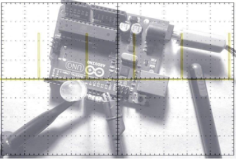
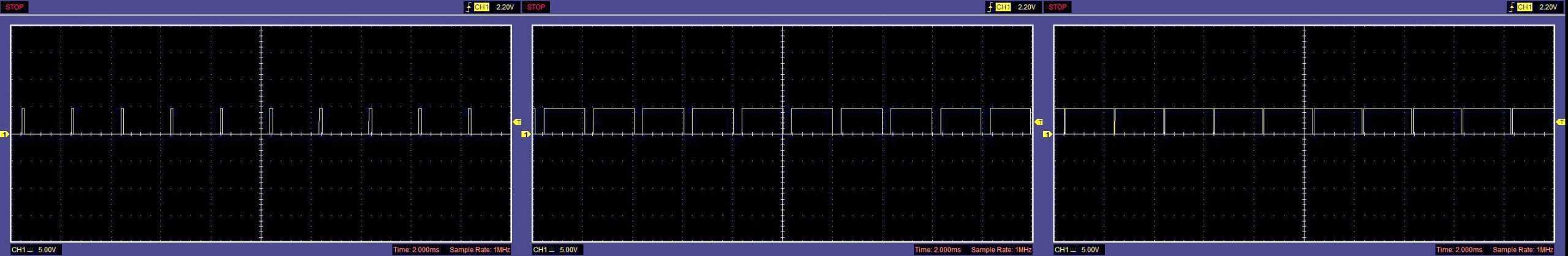
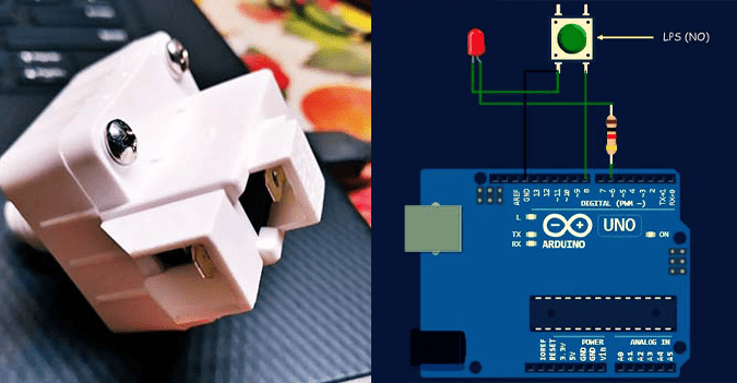
Connect an LED with a 220Ω series resistor to D9 of an Arduino Uno (one of the PWM output pins). And then upload the following code that uses the analogWrite() function to supply a variable voltage level to the LED. Thereafter you can see that the brightness of the LED changes to three levels in an endlessly repeating sequence. This allows you to verify that the PWM control of brightness is working as it should.
int LED_pin = 9;
void setup() {
pinMode(LED_pin, OUTPUT);
}
void loop() {
int dtwait = 1000; // Delay in mS
int V1=20, V2=220, V3=120; // 8-bit output values for PWM duty cycle
analogWrite(LED_pin, V1);
delay(dtwait);
analogWrite(LED_pin, V2);
delay(dtwait);
analogWrite(LED_pin, V3);
delay(dtwait);
}
Note that the classic Arduino has 3 timers – timer0 is 8 bit and used for the millis() and micros() functions (Fast PWM). Timer1 is 16 bit and not used by default, timer2 is another 8-bit timer like timer0 but not used by default. For Arduino Uno, the system clock is 16MHz so that the timers are clocking at 250kHz by default (16MHz/64). Phase correct 8-bit PWM mode takes 510 clocks to cycle and fast 8-bit PWM mode takes 256. This means a frequency of 490Hz for pins 5 and 6 and 977Hz for pins 3, 9, 10, 11 when used with analogWrite().
Arduino Advanced PWM
Arduino has implicitly set all of its PWM channels to 8-bit resolution but it’s not adequate especially when regulating the brightness of some light emitters. Luckily, 8-bit is not the maximum resolution as Timer1 can be used up to 16-bit resolution. Timer1 is the only 16-bit timer on the Amega328 and it only comes out on two pins, 9 and 10. In this session, I’ll show you how to do it.
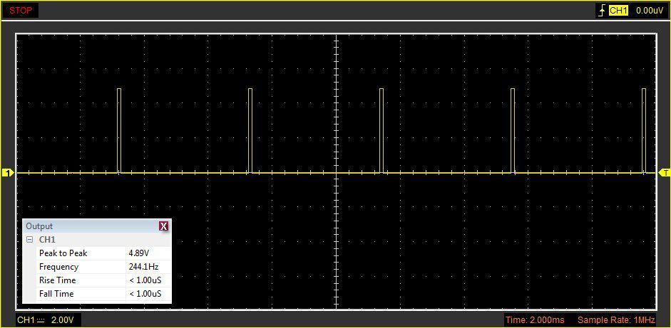
As pointed before, the default PWM on the Arduino is 8-bit phase-correct (or on timer0, 8-bit fast). But the Arduino processor ATmega328 in Uno has 2 channels from timer 1 that has two PWM registers. The maximum frequency that can be input to the timers are the Arduino clock frequency, that means 16MHz on most Arduino processors, with a 216 step PWM it implies the PWM frequency will be 16000000/216 i.e. 244.14Hz, that is fast enough for brightness regulation.
Google naturally is very useful for locating more resources, so a little Googling might help you to collect neatly written articles on direct use of ATmega328 counter/timers. With a lengthy Googling, I found a vast number of codes and libraries that give access to the 16-bit timer modes, as well as letting me tweak the PWM output frequency. Eventually, I picked a fairly simple code and adapted it for my 16-bit PWM quick demo experiment. The little code sets the 16-bit resolution and sets the brightness in low values.
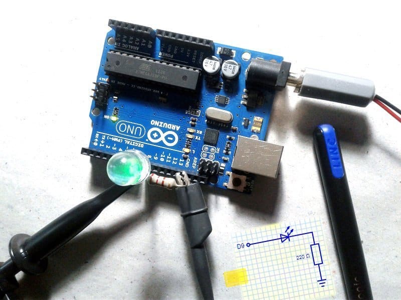
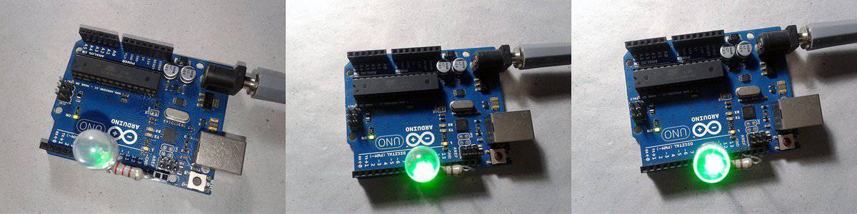
The hardware setup for the experiment is very simple. A 10mm water-clear green LED (with a 220Ω series resistor) is wired to D9, as it has the output from timer1 (you can also use D10 which is linked to the same timer1).
Below you can see the 16-bit PWM quick demo code. You don’t need a library!
/*
 * Advanced Arduino 16-bit PWM
 * Quick Demo Code for Arduino Uno & Nano
 * PWM Output Pin D9
 * Author: T.K.Hareendran/05.20
 * An Inspired Experiment - Thanks to Arduino Slovakia
 * Publisher: www.Codrey.com
 */

void setup() {
Serial.begin(9600);
setupPWM16();
}
uint16_t icr = 0xffff;
void loop() {
Serial.println("*");
for (uint16_t i = 0; i < 2000; i++)
{
analogWrite16(9, i);
delay(2);
}
}
void setupPWM16() {
DDRB |= _BV(PB1) | _BV(PB2); //Set pins as outputs
TCCR1A = _BV(COM1A1) | _BV(COM1B1) //Non-Inv PWM
| _BV(WGM11); // Mode 14: Fast PWM, TOP=ICR1
TCCR1B = _BV(WGM13) | _BV(WGM12)
| _BV(CS10); // Prescaler 1
ICR1 = icr; // TOP counter value (Relieving OCR1A*)
}
//* 16-bit version of analogWrite(). Only for D9 & D10
void analogWrite16(uint8_t pin, uint16_t val)
{
switch (pin) {
case 9: OCR1A = val; break;
case 10: OCR1B = val; break;
}
}
Yes, it worked!
Here, function setupPWM16 sets the PWM resolution. The mode and the prescaler is set to the same value as the Arduino clock signal as we’re generating a high-resolution signal. In our case, what’s highly important is the value set in ICR1. The timer will count from zero to our value and then start again from zero. The signal will be switched at this value and at the value we set in the OCR1A register. The lower the OCR1A value, the less LED will light up. In the loop function, you can see this registry setting on the first 2000 values. For further details on these settings, see timer1 in the ATmega328P microcontroller datasheet.
Be aware that every eye is unalike, hence somebody sees feebler bright changes in brightness, and some others distinguish LED flashes at a lower resolution than any other person. So we may need to tweak your final code to satisfy our eyes. Further, the eye does not see brightness linear often, however, that gets improved while using a logarithmic scale (more on later). Now note that we can ‘fine-tune’ pulse width modulation frequency and the resolution even with delimited hardware. Apparently, the pulse width modulation period put a limit point on the pulse width modulation resolution i.e. more resolution entails lower pulse width modulation frequency and higher PWM frequency at a lower resolution.
Keep going…
Now that we understand the pulse width modulation frequency (rate at which we can update the compare register, which determines the duty cycle and therefore the average value) is simply the clock frequency of the counter divided by a number of steps of the counter. We’ll have also realized by now that if we want to acquire a single PWM a 16-bit value with an Arduino at ease, we must take on a PWM frequency of 16MHz/65536 yielding the only 244Hz – not very charismatic but still have some usefulness.
If you managed to read until here, you learned how to start the play with a 16-bit PWM mode of an Arduino. There seem to be a bewildering variety of Arduino PWM tricks, I agree that it’s a bit difficult to learn. Therefore it’d be better to go through this fantabulous free tutorial firmly focused on ATmega328 counter/timers https://sphinx.mythic-beasts.com/~markt/ATmega-timers.html
Finally, it proved right that as long as only a few high-resolution PWM channels are required, then Arduino can do it on its own with very good resolution. Although I haven’t get the spark for a do it yourself project-centered exclusively on this concept as yet, I get to that later, I am sure of that.
You’re now armed! If you have any questions about this complex topic, please drop me a note in the comments. If you have any thoughts on additions or corrections, please let me hear about them as well.

> This means a frequency of 490Hz for pins 5 and 6 and 977Hz for pins 3, 9, 10, 11 when used with analogWrite().
This is backwards; pings 5/6 are the fast PWM pins 🙂
https://www.arduino.cc/reference/en/language/functions/analog-io/analogwrite/
Dave: Thanks for your valuable input.
Sorry for being so busy right now. When I get enough free time I will thoroughly check this post a second time (and will try to correct typos if any, as well).
BTW there’re dedicated Arduino libraries to generate a high frequency PWM signal on one specific output pin – not limited to 5/6 (For example, UNO’s 9,10, 3 and 11). The “FastPwmPin” is such a library (https://github.com/maxint-rd/FastPwmPin).
Hello sire. Could have, any arduino board, 16bit output on 4 pins?
E.g. on pin9, 10 and an other two more pins?
Manos: Unfortunately I don’t know, yet. Anyway take a look at Teensy microcontrollers https://www.pjrc.com/store/teensylc.html