I have already posted two Knight Rider and Larsen Scanner LED projects online. You can go through these to access them
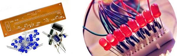
Or you can buy yourself an inexpensive Knight Rider LED Scanner Kit (see cover image) and make another version yourself. The final decision is yours!
Anyway, in this post, I will share the design idea of an I2C Knight Rider, which only needs two wires to drive up to 8 distinct LEDs. The idea is based on the PCF8574 IC which is a Remote 8-bit I/O expander for I2C-bus (https://www.nxp.com/docs/en/data-sheet/PCF8574_PCF8574A.pdf). Enjoy!
The PCF8574 consists of an 8-bit quasi-bidirectional port and an I2C-bus interface. It has low current consumption and includes latched outputs with high current drive capability for directly driving LEDs. The chip also possesses an interrupt line (INT) which can be connected to the interrupt logic of the microcontroller (not utilized in this project).
By all means, this is a simple Arduino project. Below you can see the complete schematic of the I2C Knight Rider LED Scanner.
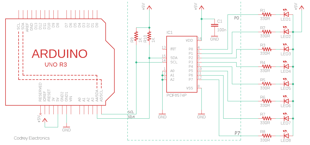
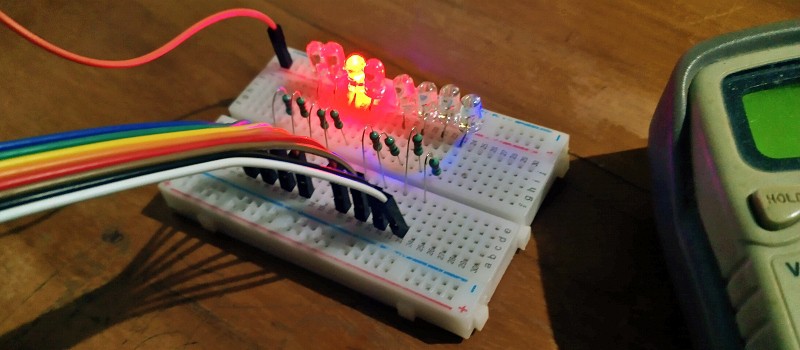
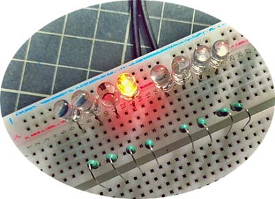
Let’s forget Arduino for a while and then focus more on the far right of the above schematic. You will now see a bunch of 8 LEDs with 330Ω series resistors and a single PCF8574 IC to control them. Besides, a pair of 1KΩ resistors are used in the circuitry to pull up the data (SDA) and clock (SCL) lines of the I2C interface.
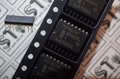
You can of course use a regular (PCF8574P) or surface mount device package (PCF8574T) of the PCF8574 IC here. The PCF8574 core circuitry is extremely simple and very easy to fabricate. Isn’t it?
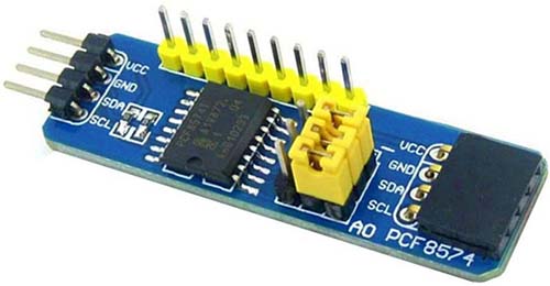
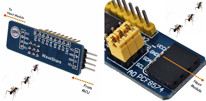
If you’re often reluctant to do soldering things (like me, ha ha), there’s a happy shortcut, that is, you can buy a ready-made PCF8574 module to minimize construction efforts. And then, simply replace the dotted part of the original schematic with your PCF8574 module. Yes, it’s done!
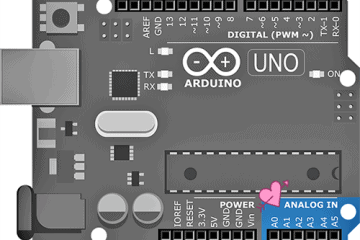
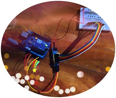
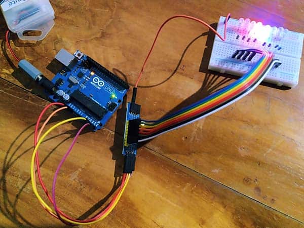
The rest is the Arduino part, but it’s quite simple. All you need is to connect the input of the PCF8574 circuit/module, that is, its SDA and SCL wires to A4 and A5 I/Os of the Arduino Uno respectively. Voila! Your 2-wire (I2C) LED Knight Rider is ready to go!
Below you can see the Arduino Sketch of my I2C LED Knight Rider. Just another lucid code snippet, that’s it!
#include <Wire.h>
#define PCF8574_ADDR (0x20) // I2C Slave Address 0x20 (A2-A1-A0 = GND)

void setup() {
  Serial.begin(9600);
  Wire.begin();
}

void loop() {
  static unsigned char data = 0x01; // LED Scan Data
  static unsigned char direc = 1; // LED Scan Direction

  Wire.beginTransmission(PCF8574_ADDR);
  Wire.write(~data);
  Wire.endTransmission();
  delay(100); // LED Scan Speed

  Serial.print("Data: ");
  Serial.print(data);
  Serial.println();
  // Shift LED in the specified scan direction
  if (direc) {
    data <<= 1;
  }
  else {
    data >>= 1;
  }
  // Check when a reverse LED scan direction is called for
  if (data == 0x80) {
    direc = 0;
  }
  if (data == 0x01) {
    direc = 1;
  }
}
At this point, note down that the PCF8574 (not PCF8574A) has I2C addresses ranging from 0x20 to 0x27. So, it can be configured to have a unique 7-bit address. The first four bits of the PCF8574’s 7-bit address are 0100. The lower three bits are the settings on the chip pins A2, A1, and A0. The PCF8574 I2C-Bus Slave Address is 20 (hexadecimal) when its A2-A1-A0 pins are tied to a ground (LOW/GND). The default slave address of a readymade PCF8574 module is also the same 0x20.
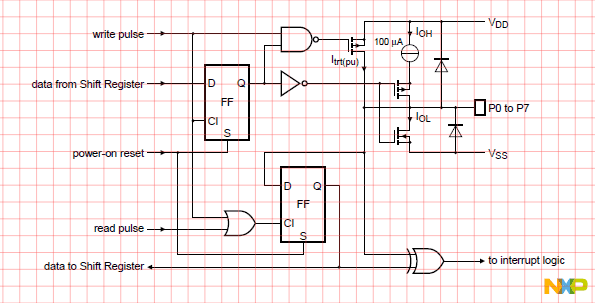
Moreover, the PCF8574 has an absolute maximum sinking current of 25mA per port pin. So, in projects requiring more drive current, two-port pins can be connected together to sink up to 50mA of current (but the total availability of port pins may be halved). Below shown is the simplified schematic diagram of Ports P0 to P7.
By the way, do you know PCF8574 (bare chip or module) can be easily daisy-chained? Yes, it’s possible because there’re three address pins that will allow you to address up to 8 PCF8574 chips/modules, and it should give you 64 I/O pins in theory. To put it simple, you can daisy-chain several of these devices together, providing each device has a unique address.
So, now you’ve the project details of a new LED Knight Rider in front of you. Now it’s your turn to go further. Make a good effort and let’s know. Good luck!