Here’s a little idea to monitor the level of water in a water tank with the help of an ultrasonic sensor module. The build process is very simple, and best understood by referring to the hardware setup diagram.
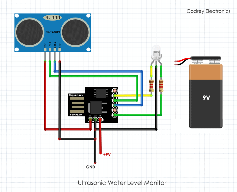
The technique behind this idea is easy to understand. The ultrasonic sensor sends out an ultrasonic pulse, waits for it to come back and depending on the time between the two events the microcontroller can then calculate the distance between the sensor and the water surface. If the water level remains above 50% of the full capacity of the tank, you should see the green light from the status indicator LED, and an yellow burning eye of the same LED otherwise. Apart from indicating the water level status, the system (if modified a bit) can also control a water pump to keep the water tank happy forever but this is obviously optional.
After initial preparation, the whole setup (with the battery pack) should be mounted inside a small waterproof enclosure with the visual indicator sticking out the top, and the two eyes of the ultrasonic sensor module look out the bottom. The sensor module must be sealed with a piece of plastic/acrylic sheet with holes cut into it to let the sensor eyes poke through. Finally, add ample amount of silicon sealant to seal the gaps and you’re ready to mount the sensor inside the collar of the water tank.
Arduino Sketch
/*
 * Ultrasonic Water Level Monitor (v1.0)
 * uC - DigiSpark
 * Sensor - HC-SR04
 * Author - T.K.Hareendran
 * Codrey Electronics - https://www.codrey.com
 */

const int trigPin = 3; //P3
int echoPin = 2; //P2
int safeLimit = 15; // see notes
// pins for status indicators (Bi-Color LED)
int alertLed = 4; // Yellow LED //P4
int normalLed = 0; // Green LED //P0
void setup() {
}
void loop()
{
//raw duration in milliseconds,
//cm is the converted amount into a distance
long duration, cm;
//initializing the pin states
pinMode(trigPin, OUTPUT);
pinMode(normalLed, OUTPUT);
pinMode(alertLed, OUTPUT);
//sending the trigger pulse, starting with LOW for a clean pulse
digitalWrite(trigPin, LOW);
delayMicroseconds(2);
digitalWrite(trigPin, HIGH);
delayMicroseconds(10);
digitalWrite(trigPin, LOW);
//setting up the input pin, and receiving the duration in uS
pinMode(echoPin, INPUT);
duration = pulseIn(echoPin, HIGH);
// convert the pulse travel time into a distance
cm = microsecondsToCentimeters(duration);
//checking if level is within the safelimit
// if not, keep alert LED on

if (cm > safeLimit)
{
digitalWrite(normalLed, LOW);
digitalWrite(alertLed, HIGH);
}
else
{
digitalWrite(alertLed, LOW);
digitalWrite(normalLed, HIGH);
}
delay(100);
}
long microsecondsToCentimeters(long microseconds)
{
// The speed of sound is 340 m/s (29 us/cm)
return microseconds / 29 / 2;
}
See component list:
- HC-SR04 Ultrasonic Sensor Module x1
- Digispark Development Board x1
- Bi-Color LED (Y&G – Common Cathode) x1
- 1K2 ¼ w resistor x2 (or 470Ω ¼ w resistors – for more brightness)
- 9V Alkaline Battery x1
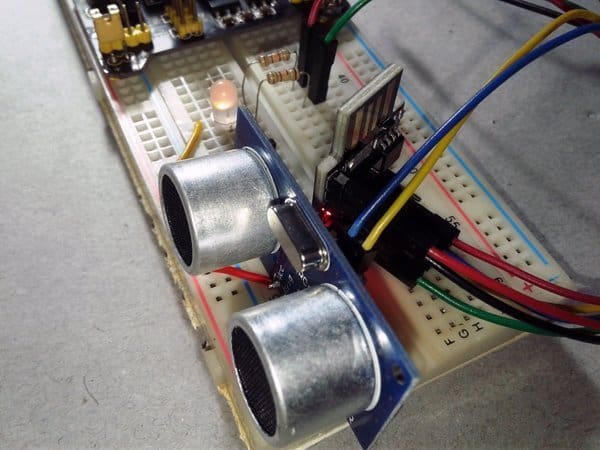
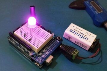
Random snap of author’s quick lab experiment:
Notes:
Refer the code line 3 “int safeLimit=15”. This denoted that the 50% safe limit is 15cm as the location of the overflow outlet in my model water tank (40cm height) is just above the 30 cm mark from its bottom. You may need to alter this value based on your real-world situation. Remember to note that the ultrasonic sensor module can measure distance up to 400 cm (with a measuring angle of 15 degrees) only!
That’s very interesting! I’ll try it
@Phil
Thanks for your feedback, and happy to see that you find it useful. Enjoy!