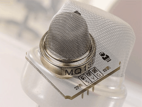
A Gas sensor serves to detect and measure the concentration of gas in the environment. Nowadays you can find many different types of easy to use gas sensors, especially in MQ series. In this article, I’m covering the MQ-135 gas sensor which is in fact a very popular and inexpensive air quality sensor.
With the increasing air and environmental pollution, monitoring air quality is getting more and more important. Did you know? Even a small raise in the concentration of carbon dioxide can cause increased fatigue, headaches or nausea. The MQ135 air quality sensor will be a good assistant here as it can provide useful information about the surrounding air. The MQ-135 gas sensor is available as a prewired module or as just the gas sensor part alone. If you’re trying to detect the presence of a gas( not measuring PPM) only then you can buy a cheap module since it comes with onboard electronics to provide a digital output signal.
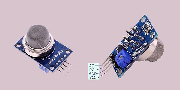
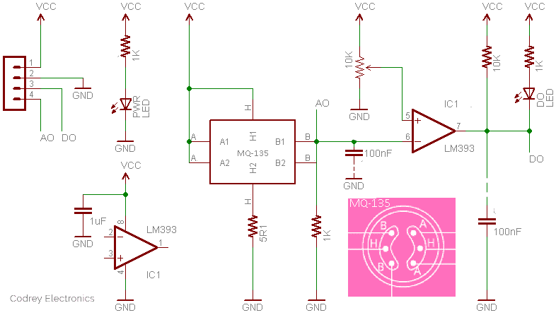
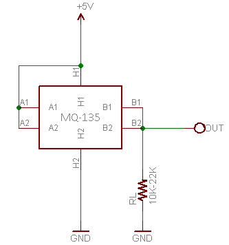
The MQ-135 gas sensor module has four pins (standard male headers) as shown above. The air quality information is readable via the AO pin. Since AO is a varying voltage, this pin should be connected to one analog input of a microcontroller. The DO pin is an open-collector digital output (but with a pull-up resistor onboard) that becomes low when the detection level exceeds a predefined level. The detection threshold can be tailored through the small trimpot soldered on the bottom of the module. Following is the generic schematic diagram of the MQ-135 module (forged by me).
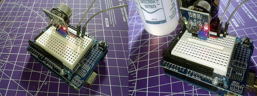
Initial preparation of the module shouldn’t present any undue difficulties if you strictly follows the procedure lined here. Well, first of all power up the module alone with a regulated 5VDC power supply. The heater of the MQ-135 sensor requires 5V and have 33Ω±5% resistance, so your power supply must render a minimum 200mA of current for the sensor part. Remember that at first the MQ-135 gas sensor have to be kept on continuously for its preheating time (over 24 hour) before you can actually play with it. Thereafter, introduce the MQ-135 sensor to the gas you want to detect and slowly adjust the trimpot until DO gets low. I tested my module with isopropyl alcohol, cigar lighter gas, perfumed body spray, and the breath of mine.
Now every time your sensor gets introduced to that gas at predefined concentration, DO will go low (0V) else will remain high (5V). Note that the green LED (OUT_LED) should also light up when gas is observed. Also note that when the sensor is powered up for gas detection, it needs around 60-120 seconds to settle, because the heater will need that much time to heat the sensor up. Remember, the MQ-135 gas sensor is suitable for detecting (or measuring) of NH3, NOx, alcohol, Benzene, smoke, CO2, etc.
If you’ve made it to this point, well done! Now you can add an annunciator of your choice at the output of the module through a suitable driver circuitry. A driver circuit is very crucial here because sink current (Isink) of the LM393 IC is just about 20mA. According to its datasheet, the maximum output current may be as high as 20mA, independent of the magnitude of Vcc, output short circuits to Vcc results in excessive heating and eventual destruction of the chip. So, an electromagnetic relay (also known as electromechanical relay) based driver is recommended here because such a driver setup can not only provide best electrical isolation but also drive other ‘beefy’ electric loads apart from a minuscule annunciator. You can either use a self-made driver circuitry for that or a readymade 5VDC (active-low input type) electromagnetic relay/solid-state relay module available for cheap.
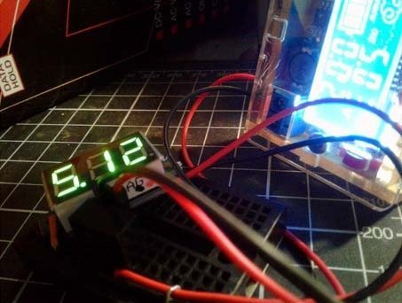
As might be expected you can take the AO output to achieve the same thing rather in a slightly different way. Try to read the AO output (0-5V) through a microcontroller so that you’ll get an output voltage directly proportional to the concentration of the gas to which the sensor is keyed to detect. This lets you experiment more with the analog output values and develop your project accordingly. Give it a good try!
This is a very bare code to read values from the MQ-135 module with its AO connected to A0 of an Arduino Uno. The values read from the sensor is proportional to the air quality measured by the sensor, and it’s displayed on the serial monitor. Remember to use a separate 5VDC power supply for the MQ-135 module (as mentioned earlier) but firmly join their ground rails (GND) together so that they can work with a common ground connection.
int sensorValue;
void setup()
{
Serial.begin(9600); // Baud rate 9600
}
void loop()
{
sensorValue = analogRead(0); // Read analog input pin A0
Serial.println(sensorValue, DEC); // Print the value read
delay(1000);
}
Analog way (ppm)? It’s not an easy walk!
Are you getting unreasonable analog readouts? Don’t worry, we’re now going to take a close look at the MQ-135 gas sensor in this session.
The MQ-135 gas sensor has an inbuilt variable resistor (sense resistor) that changes its resistance value according to the concentration of gas. If the gas concentration is high, the resistance decreases, and if the gas concentration is low, the resistance increases. The MQ-135 gas sensor basically needs only one key component as the external component – just a load resistor. The load resistor serves to adjust the sensor’s sensitivity and accuracy. The value can range anywhere from 10KΩ to 47KΩ (the higher the resistance, the more sensitive the sensor becomes). Since sense resistance (Rs) value of MQ-135 gas sensor is different for various kinds and various concentration of gases, sensitivity adjustment becomes very necessary.
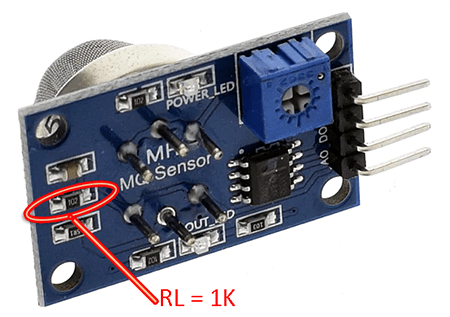
The datasheet recommends to calibrate the MQ-135 sensor for 100ppm NH3 or 50ppm Alcohol concentration in air and use value of the load resistor (RL) about 20KΩ (10KΩ to 47KΩ). But in the MQ-135 Chinese module introduced here, we can see a 1KΩ (102) load resistor. Not a good practice of course!
So if you want to build a microcontroller-based trusty air quality monitor yourself with MQ-135, you should replace the 1KΩ load resistor with one 10-22KΩ load resistor to get appropriate readings. By the way, it’s worthy to note down the acceptable CO2 ppm values:
- 400ppm – 750ppm: Good for health
- 750 ppm – 1200 ppm: Take care
- 1200 ppm (and above): Harmful to health
Next figure depicts the typical sensitivity characteristics of MQ135 gas sensor for several gases. That means the given plot tells us the concentration of a gas in part per million (ppm) according to the resistance ratio of the sensor (Rs/Ro). Here, Rs is the resistance of the sensor that changes depending on the concentration of gas, whereas Ro is the resistance of the sensor at a known concentration without the presence of other gases, or in the fresh air.
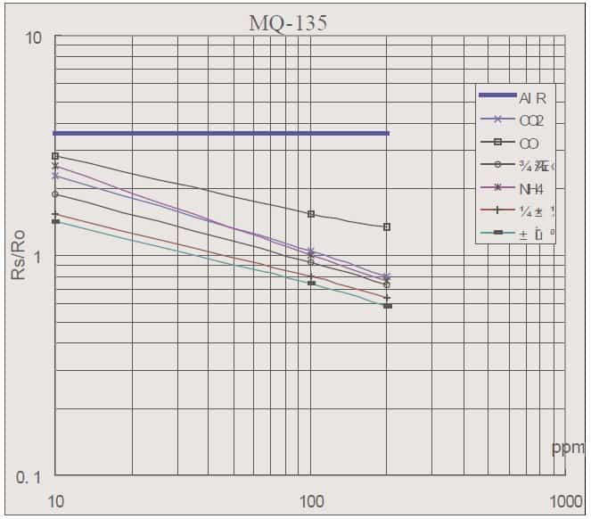
In this sensitivity characteristic curve (borrowed from the datasheet), Ro is the sensor resistance at 100ppm of NH3 in clean air, and Rs is the sensor resistance at various concentrations of gases.
If you want to do anything serious with MQ-135 gas sensor, then you should learn to analyze this plot pretty well. However that needs some skill and patience as the scale is log-log i.e. in a linear scale, the behavior of the gas concentration with respect to the resistance ratio is exponential (not linear). For determining Rs/Ro, you can use the fact that the Rs/Ro ratio is a constant in clean air. Also, by definition, only the Rs changes when a gas is present while Ro remains constant. Therefore, if you can determine the value of Rs in clean air, you can also determine Ro and ultimately Rs/Ro. A bit indigestible for a novice, but I’ll try to shed some light on it later. Meanwhile simply note that in science and engineering, a log–log plot is a two-dimensional graph/plot of numerical data that uses logarithmic scales on both the horizontal and vertical axes (https://en.wikipedia.org/wiki/Log–log_plot).
As discussed in the beginning, if you only want to detect the presence of a gas in your surroundings then you can simply use the cheap MQ-135 module and use its DO output as explained. On the other hand, you’re in need of a precise ppm count then it’d be better to use the MQ-135 gas sensor alone as shown below, the analog route (especially the sensor calibration and associated maths) is somewhat tough though (but there’s no shortcut)!
In principle, MQ-135’s internal sensor resistor RS and external load resistor RL forms a voltage divider. In the datasheet we can see that the sensor resistor has a value of 30KΩ-200KΩ (100ppm NH3). And, as pointed on the log–log plot, RS in fresh air (under certain temperature and humidity) will be a constant value.. The main part of the calibration is to calculate the RO by sampling and averaging the readings when the gas sensor is placed in fresh air. Once the RO is derived, Rs value can be calculated.
Naturally, an Arduino microcontroller can be used to read analog values outputted by this setup, and it’s not very hard because there’s one simple library (from G.Krocker) prepared for Arduino platform (https://github.com/GeorgK/MQ135). With its help, you can do some experiments along with the Arduino code snippet posted here https://blog.robberg.net/mq-135-arduino/. You’re free to use the AO output of your MH-135 Chinese module as well, but you might need to change its load resistor to 10KΩ (or much better 22KΩ).
While using the library-supported Arduino setup, MQ-135 gas sensor calibration is done at first by finding the value of Ro in fresh air, and then using that value to find Rs through the formula: Rs = (Vcc/VRL-1)x RL, that means Rs = (5V/(sensorValue * (5.0/1023.0))-1)*RL. Anyway, I’m not feeling comfortable with the MQ-135 gas sensor library/math/code and still got a few things for my next homework.
But a moment, I welcome your follow-through on this:
- Download the MQ135 Library and include it in your Arduino IDE
- Prepare the hardware setup with MQ-135 gas sensor and 10KΩ Load Resistor (RL)
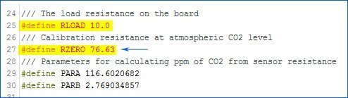
After the 24 hours preheat process, perform the following procedures in the environment of 20 degree C/35% air temperature, and read the value of RZERO
#include "MQ135.h"
const int ANALOGPIN=0;
MQ135 gasSensor = MQ135(ANALOGPIN);
void setup(){
Serial.begin(9600);
}
void loop(){
float rzero = gasSensor.getRZero();
Serial.println(rzero);
delay(1000);
}
- Insert the resultant value in the “MQ135.h” file in the MQ135 Arduino library file
- Start monitoring air quality
#include "MQ135.h"
const int ANALOGPIN=0;
MQ135 gasSensor = MQ135(ANALOGPIN);
void setup(){
Serial.begin(9600);
}
void loop(){
float ppm = gasSensor.getPPM();
Serial.println(ppm);
delay(1000);
}
Take note, my basic Arduino Uno setup was tested with a modified Chinese MQ-135 module (10KΩ load resistor) and ofcourse it’s supported by the MQ135 Arduino library (RZERO value updated accordingly). In the MQ135 Arduino library, the atmospheric CO2 level for calibration purpose is defined as 397.13 ppm but I think nowadays that reference value needs an uptick (https://www.sciencedaily.com/releases/2019/06/190604140109.htm).

Thanks for reading with the utmost patience!


the RLOAD its 10000 or 10 ?
and how we calculate R0 ?
thanks !
yassin: RLOAD 10000 is for 1oK Load Resistor!
As clearly pointed in this post, while using the “MQ-135” library-supported Arduino setup, the gas sensor calibration can be done at by finding the value of Ro in fresh air, and then using that value to find Rs through the formula: Rs = (Vcc/VRL-1)x RL, that means Rs = (5V/(sensorValue * (5.0/1023.0))-1)*RL.
I tried to make this primer very readable and self explaining and provided lots of pointers. If you want to know more, look at http://davidegironi.blogspot.com/2017/05/mq-gas-sensor-correlation-function.html
thank you bro ! but i show
#define RLOAD 10.0
not
#define RLOAD 10000
i have to divide by 1,000 or what ?
Hi, I’m trying to implement this with an ESP32, but the readings of A0 from the sensor are in miliVolts (it varies from 14 mV to 30 mV). The ESP can’t read mV so assumes that the input is 0V.
I tested my MQ135’s analog output with a digital voltimeter to be sure and the outputs are in mV.
What I’m doing wrong? I need to change load resistor or is just that my MQ135 is defective?
Thanks
Matias: First off, note that note that all MQ-135 sensor has to be powered up for a pre-heat duration for the sensor to warm up before it can start working. This pre-heat time is normally between 30 seconds to a couple of minutes. So, when you power up the module leave it in that state till the pre-heat duration is completed.
On paper, the analog level output provides an output voltage within the range of 0 to 4V approx. based on the concentration of the hazardous gas in the environment (0V for lowest concentration, 4V for maximum concentration).
Further, as you might noticed while reading the datasheet that the load resistor value is 2 kΩ to 20 kΩ, and the test circuit shown there is really just forming a voltage divider from the 5V supply with the lower end being the load resistor (RL).
Therefore, If you select load resistor as 1kΩ when the sensor’s resistance is 2 kΩ the output will be 1.66 V which you can directly connect to your ADC.
Hope these links may help you further. Thanks!
https://iotbyhvm.ooo/interface-mq135-gas-sensor-with-nodemcu/
https://www.electroniclinic.com/iot-smoke-detector-using-mq135-gas-sensor-nodemcu-esp8266/
What is your power source for MQ135? And what voltage is that power source? Is that power source capable of outputting at least 20 mA? And finally, Do you have common grounds (between MQ135 power and ESP32power)
@Chuck Merja: Hope you get answers from @Matias. Thanks!
Hi,
Thank you for this!
I am using the MQ-135 sensor but unmodified (1k resistor) Will this still work fine?
Next the value 76.63 that you entered into the header file was that the value you got from the equation? If I am using the 1k resistor would that be the RL value?
Dom: You’re welcome!
Probably, 1K will be fine for certain applications. You may look at the post again as I made it very readable and self explaining and provided enough pointers.
BTW I tried my module with 10K load resistor as clearly pointed in the writeup.
If you want to know more ,I will leave you with a great post for the details – http://davidegironi.blogspot.com/2014/01/cheap-co2-meter-using-mq135-sensor-with.html
Thanks!
Thanks so much for this article. One very-n00b question: do I need to add a resistor if I just want to run a circuit to this sensor, or does the internal resistor do enough to protect the component. Thanks!
Taylor: Welcome & Thank You!
As you might noted, the enveloped MQ-135 have 6 pins – 4 of them are used to fetch signals, and other 2 are used for providing heating current. Here, the series resistor (5R1) in the module schematic (Fig 3) is not very crucial, but the load resistor (1K in the schematic) is essential. As mentioned, its value should be in the 10K -47K range.
Further reading: https://jayconsystems.com/blog/understanding-a-gas-sensor
Hello T.K. Hareendran,
Thank you for this great post. I can see it’s been useful for a lot of people trying this MQ-135 around. I’ve found the information you posted here very useful and handy.
Have you noticed that George Krocker library (MQ135.cpp) needs a correction in the “getResistance()” formula? There, the formula is:
((1023./(float)val) * 5. – 1.)*RLOAD
and I think it should be:
((1023./(float)val) – 1.)*RLOAD;
Another question, have you tried this library directly with several sensor/modules? I am wondering if the parameters calculated by Gironi and implemented in Krocker’s library are good enough as a general approximation for these sensors.
Regards!
Hello Henry
My pleasure, thanks for your inspiring feedback.
In fact, while preparing this post, I saw a lot of discussion about GeorgK’s MQ135 library errors (https://githubmemory.com/repo/GeorgK/MQ135/issues).
That is why in this article I have indirectly expressed my displeasure about the library. I’ll take a second look at it when I get enough free time. BTW your maths seems okay at this moment.
Sadly, I’ve not yet reached an in-depth inspection of the MQ135 gas sensors and modules. Maybe I will come up with more useful project documentations later.
The next tryout may be with the MQSensorsLib (https://github.com/miguel5612/MQSensorsLib).
Thanks again for taking the time to share many valuable pointers 👍
Hi,
Thank you for this web page.
Just a question about this step : After the 24 hours preheat process, perform the following procedures in the environment of 20 degree C/35% air temperature, and read the value of RZERO
To get RZERO , I read value immediatly on a cold start of the MQ135 or I need to wait for a hot value after power up after 5mn?
Regards
Richard
Klein: One of the main challenges of this experiment is calibrating the sensor. There’re multiple ways to calibrate the sensor but the sensor is extremely sensitive, and it needs to be done under the exact conditions that the MQ-135 sensor application manual recommends.
Coming to your question, it’s observed (by me) that, after the preheat process, MQ-135 gives more stable results around 3 minutes after the power up (initial heating interval after powerup). To put it simply, it seems MQ-135 sensor needs some time in order to reach its chemical equilibrium after every power cycling. So, you may wait for 5 minutes.
Thanks!
What is VRL in Rs = (Vcc/VRL-1)x RL?
Anton: VRL is the voltage of load resistance RL.
See page 4 of this datasheet for more https://www.winsen-sensor.com/d/files/PDF/Semiconductor%20Gas%20Sensor/MQ135%20(Ver1.4)%20-%20Manual.pdf
Hi, how did you modified the load resistor of the MQ-135?
I can’t find anything about that.
Thank you!
Mytharrd: Simply pick your soldering iron, and replace the 1KΩ (102) resistor with a new 10KΩ (103) resistor. The image (https://www.codrey.com/wp-content/uploads/2020/01/MQ135-Load-Resistor-Location.png) included in this post illustrates that clearly!
Many thanks for a great job and vivid explanations
Please for Honeywell Sensor Assembly(SIEGER P/N 000705-A-1733), Series 705, is there quick test of the sensor only without the Module(Detector Micro-controller) to ascertain that the sensor is good(functional) using a power supply and a Fluke Calibrator to read out the AO.
Herewith my questions
1. Can you confirm that the 3 cable connection is ok if connected this way
Sense – Brown – Output ?
0v – White
Ref Blue +Voltage?
Hence do you require the Rs and Ro just to confirm that the “Sensor Only” is ok?
Can you connect 5V directly as indicated and measure output voltage say 0-4v using Fluke 754 Calibrator that has a 250 ohm resistor without Rs or Ro
Thank you once more for your great and clear explanation give freely on this subject.
Frank: Sorry, I have no idea about this yet.
But hope this helps https://prod-edam.honeywell.com/content/dam/honeywell-edam/sps/his/en-ca/products/gas-and-flame-detection/documents/705_HT_Combustible_Sensor_Quick_Start_Guide_MAN0625.pdf Thanks!
I want to use mq135 and also the esp32. But the problem is, i dont find any code to calibrate this sensor. And i want to connect this mq135 with relay to switch off/on based on the threshold that i want. Can you help me? Anw nice explaination!
@Ander:
Haven’t tested MQ135 with ESP32 yet, so can’t give practical suggestions.
Sorry, but hope this helps https://github.com/maaz-siddiqui/ESP32_MQ-135_SH1106
Thanks!