What should you do when you hear a midnight door knock? Although there’s no quick answer to this question, you must keep in mind that you and your locked door may be the only obstruction standing between some really risky people and your sleeping family. Perhaps, a midnight door knock might just be ‘confirmation trick’ of an experient robber trying to break into your home. So do not open the door even if you’re armed! However, don’t simply sit back down to watch the consequences. Make a call to the police emergency/helpline number and follow their advice.
That’s okay but think of a scenario where someone knocks, while you’re in deep sleep, and you just don’t hear that noises unless the impact wakes you up (https://psychcentral.com/lib/stages-of-sleep/). Beware, if it’s at the backdoor of your house, possibly you’re in imminent danger, as there’s an extremely high probability that an intruder (or a team) is attempting to break into your house (https://www.survivalsullivan.com/someone-knocks-door-middle-night/).
Midnight security alarm/light controller
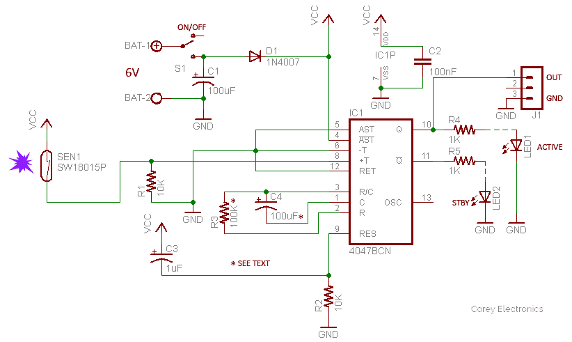
Here’s the do-it-yourself project of a midnight security alarm and light controller realized with the help of highly available and cheap electronics components. This multipurpose electronic security alarm/light controller with a great shock/vibration sensor at its heart does its job while you sleep and want to know if someone is about to enter inside. Once you secure this device on the rear side of a door, if anyone knocks/breaks the door, the device wakes up instantly. Since the linked up security alarm/siren (and lights) go off concurrently, you’ll know someone tries to make an entry without right or permission.
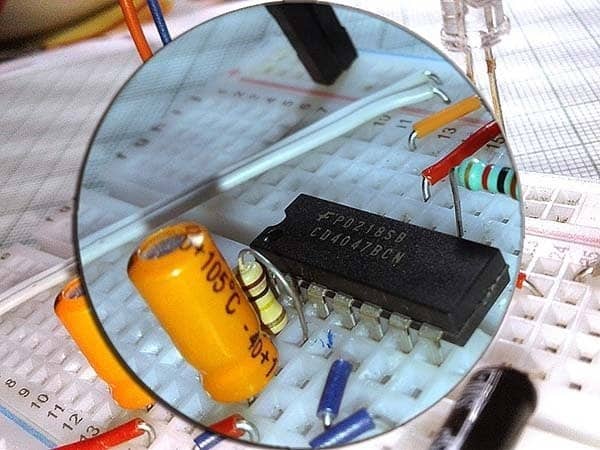
The simplified design presented here is centered on a quite popular CMOS low-power, high-voltage type, monostable/astable multivibrator chip – the CD4047B.
Here, the CD4047B IC is wired as a monostable multivibrator configured to run from a 6VDC (battery) power supply source. The key component that works together with the monostable circuit is a cheap vibration sensor SW18015P. Following is the entire schematic of the midnight security alarm & light controller.
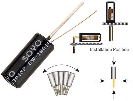
The SW-18015P is a completely airtight, spring type, no directional vibration sensor trigger switch. Its key electrical characteristics are listed below (courtesy – http://www.blswitch.com):
- Voltage: <12V
- Current: <50mA
- Conductive Time: 2ms
- Open Resistance: >10MΩ
- Closed resistance: <30Ω
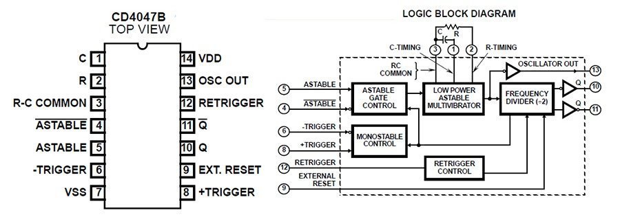
Below is the pin out diagram and logic block diagram of CD4047B. It’s prepared with the help of excerpts taken from a datasheet published by SYC (www.sycelectronica.com.ar). As you can see there, the CD4047B chip consists of a gatable astable multivibrator with logic techniques incorporated to permit positive or negative edge triggered monostable multivibrator action with retriggering and external counting options
Working of the circuit is simple and straight forward. During initial power up, the monostable (IC1) is resetted by the power-on-reset components R2 and C3. As a result, the Q output of IC1 (pin 10) remains in logic-low state, and its complementary output (Pin 11) delivers a logic-high output. As a result, LED1 stays in off state and LED2 remains lit to indicate the standby state.
When the SW-18015P vibration sensor (SEN1) gets fired by a shock/vibration, the CD4047B monostable multivibrator (IC1) is triggered and LED1 lights up instantly to indicate the active state. Simultaneously, IC1 delivers a logic-high level output through its Q output for a certain duration (~24 seconds) determined by the in-circuit values of RC timing components R3 and C4. Just after the time interval (2.48xR3xC4), the entire circuit returns to the idle/standby state until it gets triggered again by another impact. Note that the recommended values for RC timing components R3-C4 should be C> 1KpF, up to any practical value, and 10KΩ < R <1MΩ.
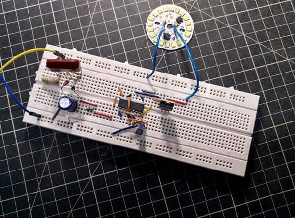
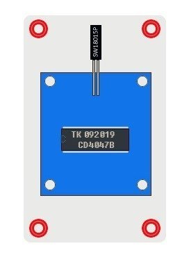
Following is a quick snap of my initial breadboard setup which is ‘open to improvement’. Later, the circuit was built on square of perfboard. Although the whole circuit was originally put together quickly as a proof-of-concept, it’s been in use for quite some time in my lab.

A few more words…
Now you’ve a pretty smart midnight security alarm/light controller good enough not only to pre-warn you of an attempted break-in or unauthorized entry especially in the middle of the night, but also to deter the assailant. You should combine a loud (~120db) ear-splitting siren (and warning lights, if necessary) with the multi-purpose alarm controller circuit finally to make a great inexpensive midnight security alarm system with some extra bells and whistles. I’m sure, even a beginner can get his/her first prototype up and running within an hour.
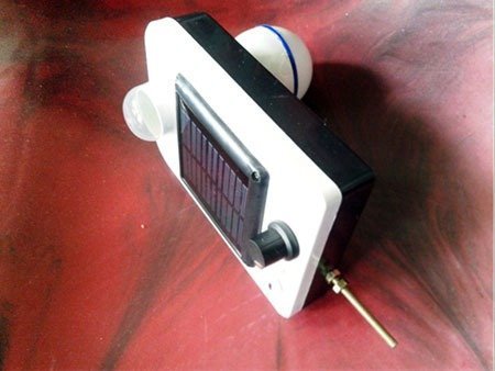
Remember, your final build must contain pretty much everything you need to get it run, from a small enclosure and battery pack through the hardware for mounting the construct securely on the door. The vibration sensor must be soldered directly on one edge of the circuit board housed in the enclosure (see next figure) so that ‘feel of the impact’ excites it decently.
Nevertheless, I’d recommend that the circuit is powered by a healthy battery pack if you intend to leave it running unattended for several months at a time. I used a combination of standard dry cells with astonishingly good results!