Not long ago, we published an article related to this topic. This time the prime aim of this revised article is to serve as inspiration for electronics hobbyists who are making projects which involve driving junk box bipolar stepper motors.
Let’s start with the lead picture of a linear motion guide rail, that’s used commonly in many mechatronics projects to translate turning motion into linear motion.
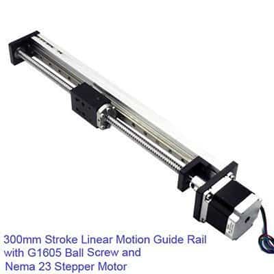
As you can see, the pictured product is an ingenious device that has a precision stepper motor and a ball screw (https://www.wikiwand.com/en/Ball_screw) as its primal parts. Simply one interesting and useful thing to buy but see it’s priced at $125 (https://imall.com)!
Fortunately, for a hobby-level project, you can simply omit such a pricey device just by lifting a small bipolar stepper motor from an unused CD/DVD drive. Probably what you get then is a combo of a bipolar stepper motor and a leadscrew (https://www.wikiwand.com/en/Leadscrew)!
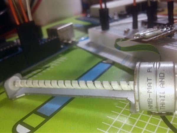
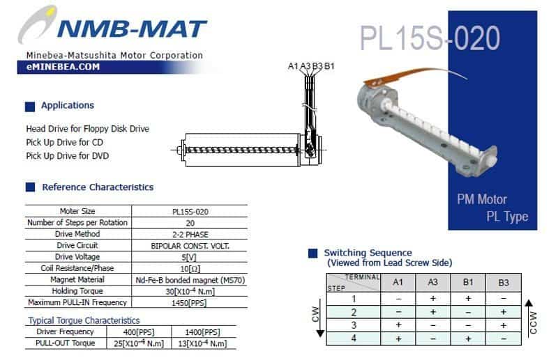
Image of such a combo is shown above. I got it from a salvaged optical disc drive of an old LG desktop computer. The “PL 15-S020” stepper motor in that assembly is a 5VDC, 2-phase, 20 steps/revolution type mini bipolar stepper motor from NMB-MAT.
This session is meant to help novices understand how to drive a standard bipolar stepper motor. There’re two types of steppers: unipolar and bipolar, and in extreme basics, a bipolar stepper motor has two coils and four wires.
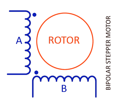 Stepper motors effectively have multiple ‘toothed’ electromagnets arranged around a central gear-shaped piece of iron. The electromagnets can be energized by an external stepper motor driver circuitry. Since a 2-phase bipolar motors have a single winding/coil per phase (2 leads per phase), the current in a winding/coil needs to be reversed in order to reverse a magnetic pole. The typical one drive cycle pattern of a 2-phase bipolar stepper motor would be: A+ B+ A− B−, that means drive coil A with positive current, and then remove current from coil A. Next, drive coil B with positive current, and then remove current from coil B. Next, drive coil A with negative current, and then remove current from coil A. Finally, drive coil B with negative current (see below).
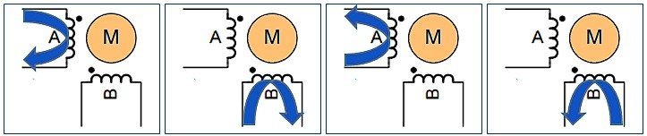
This obviously calls for a bit more complex driver circuitry, and typically looks for an H-bridge setup (simply, a set of four transistors that can pull each wire high or low). However, the abundance of dedicated off-the-shelf motor driver chips means that’s much less hard to achieve.
Have in mind that the popular driving modes of a stepper motor are full step and half step. The full step can further be divided into one-phase and two-phase mode. In ‘full step one-phase’ mode the driver energizes single coil at a time, while in ‘full step two-phase’ mode the driver energizes both coils simultaneously.
The stepper motor driver circuitry delivers command pulses at specified rates so that pulse moves the stepper motor one step, signifying that ‘pulses per second’ translates to ‘steps per second’.
If you’ve one stepper motor with command pulse rate of 20 per second and a step angle of 18 degree, the rotation per minute (RPM) will be “ 60 [ (pulse rate) ÷ (steps per revolution) ] “.
Here, the number of steps in one (360 degree) revolution is “360/18 = 20 steps per revolution”.
Therefore, the RPM will be “60 [ (20) ÷ (20) ] = 60(1) = 60 RPM “. Did you get the maths?
Quite naturally, you’ll want to test/evaluate the eligibility of your ‘salvaged’ two-phase bipolar stepper motor before actually putting it into your next project. But how? Luckily, you can use the L293D quadruple half-H driver chip which can work as a dual H-bridge driver, with an Arduino Uno at ease. The following image shows the pretty simple circuit diagram of the bipolar stepper motor driver based on L293D.
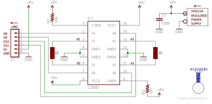
As you can see in the above circuit diagram, The L293D (IC1) chip has 16 pins with 4 control inputs (1A-2A-3A-4A) and 4 drive outputs (1Y-2Y-3Y-4Y). The 4 drive outputs are connected to the coils (L1-L2) of the bipolar stepper motor while the 4 control inputs are connected to 4 I/Os (D8-D11) of Arduino Uno as pointed out in the circuit diagram. The entire hardware setup must be powered from a proper external power supply, to say, one 5VDC/1A well-regulated power supply system. The Arduino board’s 5VDC output shouldn’t be used!
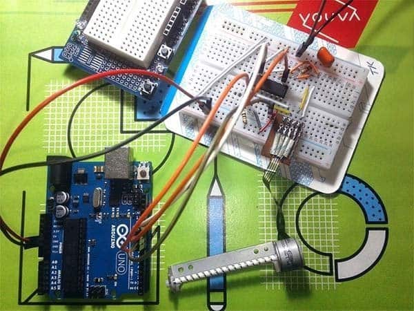
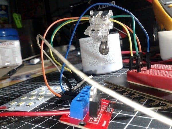
Following is a casual snap of my quick test setup devised on a small 400 tie-point breadboard:
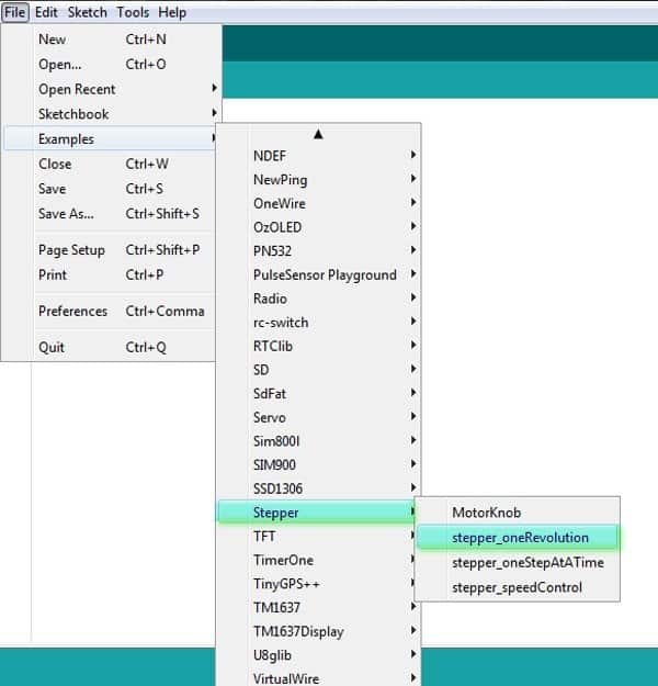
In order to carryout the quick test, you too can seek the help of Arduino’s inbuilt stepper motor library which provides simplified (and well-commented) example codes (see below). At first, I used an adapted version of the ‘one revolution’ example sketch where the bipolar stepper motor should revolve one revolution in one direction, and one revolution in the other direction, endlessly (watch my quick test movie).
The bipolar stepper motor used here is ‘intentionally’ an old one lifted from a defunct personal computer compact disc drive as mentioned before. That’s because this article is meant to get you started with salvaged bipolar stepper motors laying on your junk box, such as small stepper motors borrowed from magnetic drives and optical drives.
It’s hoped that now you know much more on how to recycle a ‘rust-brown’ bipolar stepper motor situated somewhere, how to find its key characteristics by Googling the part number, and how to examine it speedily with a dedicated motor driver chip (ofcourse through a microcontroller). Regardless of the type and size of the stepper motor the basic working principle of all the stepper motors is exactly the same. There are many ways for driving unipolar/bipolar stepper motors, and you’d probably be better off learning various stepper motor control techniques, and trying/building advanced circuits for smooth, safe, and accurate control. Any thoughts?
Addendum
Small bipolar stepper motors of this type typically have a phase resistance of 10-12Ω. Since on 5V this accounts for 400-500mA, the power supply system must have the ability to cater more than that current. Further, this type of small bipolar stepper motors (used in computer disc drives) have one of the shaft bearing on the end of the shaft, and the other inside the motor. So, if it’s out of the drive frame, the rotor might not spin properly. And perhaps will get jammed!
Nice article. I have a few unused motors lying around and will probably try to do your project as described.
Thanks for sharing.
@Shashi Kiran: I’m happy to see your positive remark here. Get creative!
Thanks!