One issue that has caught quite a few electronics hobbyists out when they build simple projects on a breadboard is the selection of a right power supply source. The most popular MB-102 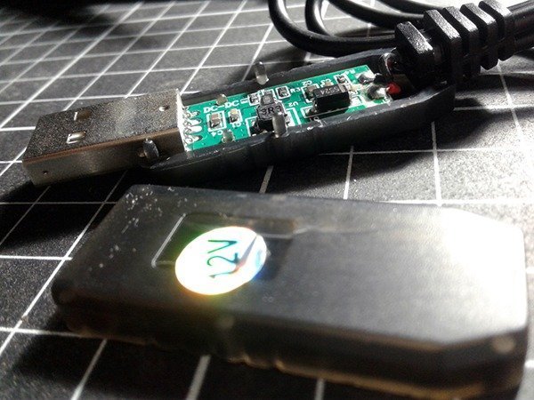 breadboard comes with an optional regulated, dual-channel, breadboard power supply module but the trouble is that it requires one 9-12VDC external power supply unit. I still advocate that 5V breadboard projects be powered with good quality, high capacity, mobile phone power banks as you get the advantage of ample runtime, and efficient circuit protection. However, in certain situations, usage of the power bank is not a viable solution as it can’t cater enough (high) voltage for a project that has power-hungry output loads like motors and/or actuators. In this post, I show you just another idea to use a common power bank in such cases by means of an easily available cheap power supply accessory – the USB 12V Cable!
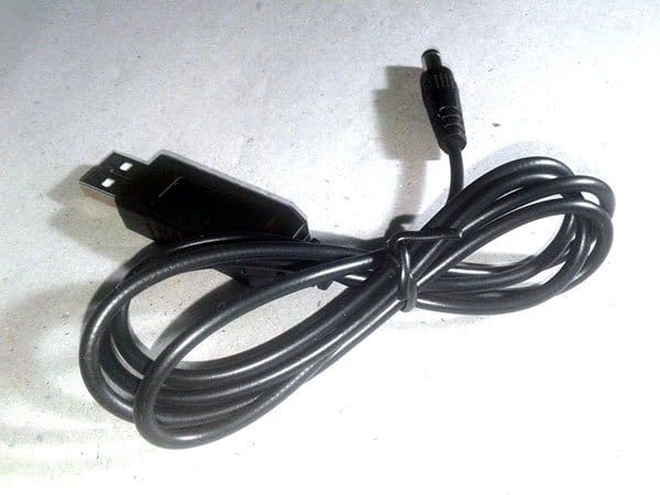
The USB 12V Cable
Since a mobile phone power bank is a feature-rich source of healthy 5VDC supply, we can safely attach one dc-dc boost converter circuit to its output to get desired dc voltage outputs moderately higher than that of the nominal 5VDC. Recently, while searching for some power supply devices, I accidentally came across an astonishingly cheap USB 12V Cable, and bought a pair myself from an Indian online electronics store as it seemed like a pretty nifty power supply step-up accessory.
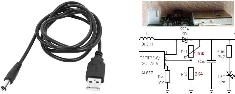
Output end of the USB 12V cable has a molded dc barrel male connector to output the 12VDC supply. Input end of the cable has a USB ‘A’ male plug protruded from the translucent USB shell which also houses a small dc-dc boost converter circuit board inside.
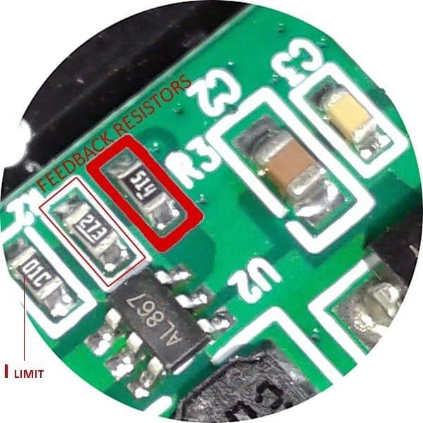
Here you can see the PCB which seems pretty simple. Given that the device doesn’t have a circuit diagram online, newcomers may feel a little bit lost. As a result, I might as well give you a few lines to help you know more about its inside electronics.
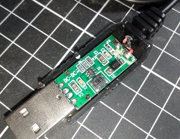
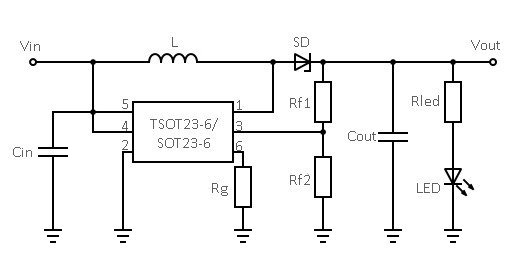
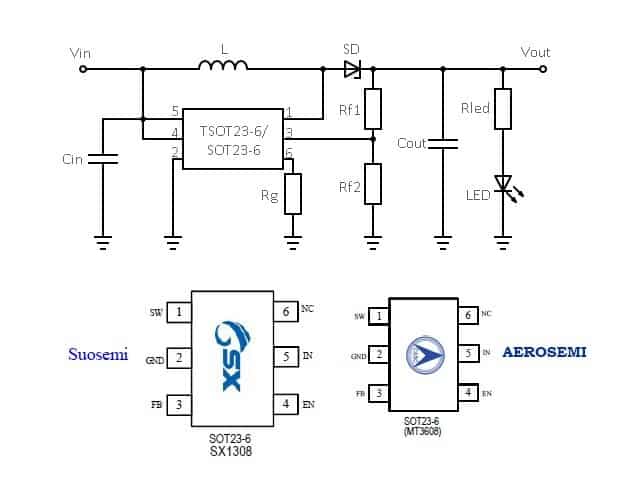
Although the IC has a part number marked as AL867, the entire design closely resembles the typical application example of SX1308 (Suosemi), and MT3608 (Aerosemi) 1.2MHz, 2A, Step-up Converters. Perhaps, the chip might be another make but with the same electrical characteristics!
Note that, value of feedback resistors in the circuit are chosen for an output of 11.9VDC. And, what you get at the output is exactly 11.9VDC in no-load condition.
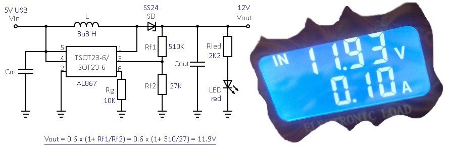
Only one strange component appeared in the PCB is a 10K SMD resistor (01C) wired between pin 6 of the chip and ground rail. It’s not been mentioned anywhere in any datasheet, however, I was informed that it’s included intentionally to limit the input current draw to 1.2A maximum.
An Agile Test
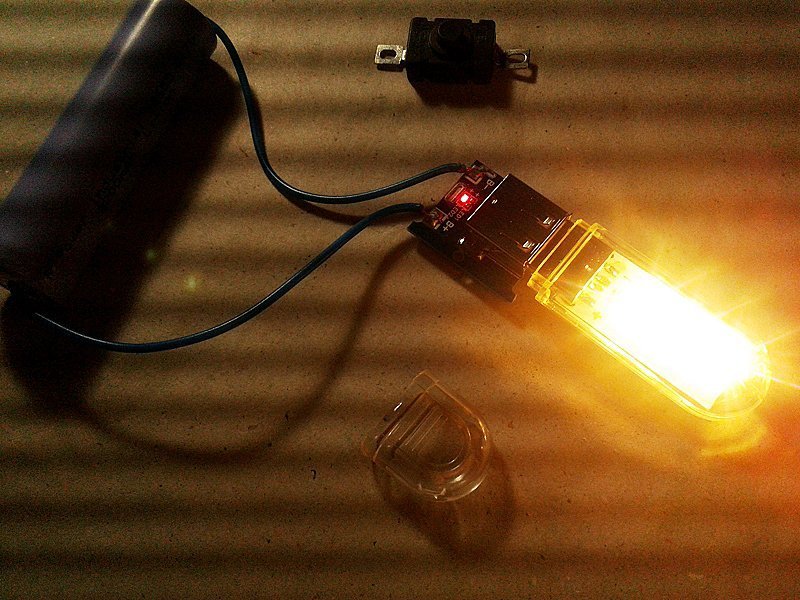
Having thoroughly explored the circuitry of the device, lets take a look at its real-world performance. Since the only way to know how well it performs is to test it out, I powered up the USB 12V cable by a power bank and wired an electronic load across its output. I also used a USB power monitor in the test/evaluation setup to watch all input-side activities.
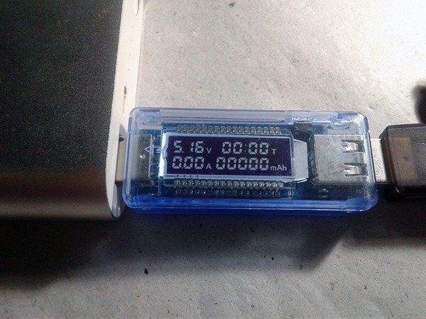
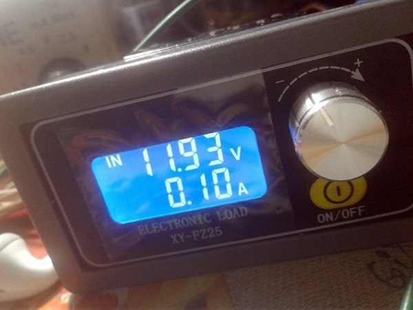
Now to the test report: At first, the USB 12V cable successfully delivered 100mA of load current at 11.93VDC output when powered by 5.16VDC supply available from the power bank. That’s right as expected!
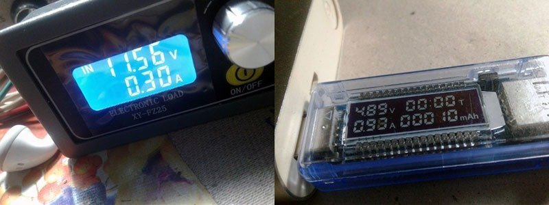
Anyway, the output voltage dropped to 11.56VDC at 300mA load current. The power bank’s output voltage also dropped to 4.89VDC because the cable’s current consumption was around 1A. And finally, the power bank got switched off (shutdown) when the output current draw crossed 350mA mark (the observed input/cable current consumption was above 1.2A at that time)!
The below table will now summarize the quick test report:
| O/P Load Current | O/P Load Voltage | Power Bank O/P | Remark |
|---|---|---|---|
| 100mA | 11.93V | Nominal 5.16V | |
| 300mA | Dropped to 11.56V | Dropped to 4.89V | |
| >350mA | Dropped to 0V | Dropped to 0V | Power Bank Shutdown |
Does it hit the mark?
USB 12V cable is a cheap molded power supply cable which boost the input voltage without an external electronics circuitry. You simply plug the cable on your power bank and it delivers 12VDC from available 5VDC. Okay, but does it work that easily?
There are obvious “pros” as not having to fiddle with external hardware is a major plus, especially if you’ve found that to be cumbersome. The fact that it is compatible with any power supply device that has a USB output makes it quite versatile. The boosted output voltage is pretty stable, depending on your load configuration, and it is small enough to take with you.
There are also a few “cons” to consider. The first thing to realize is that the USB 12V cable was never designed to deliver output current greater than 300 mA at 12VDC. I found that the best configuration is using the cable for powering up loads that require 250mA or less at 12VDC. Although the claimed efficiency of the USB 12V cable is close to 93% (see seller’s claim below), I found that it’s far below than that!
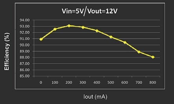
(The true electrical efficiency of a power supply can only be determined by measuring the average input and output power over a period of time. Lacking time or equipment, you can only make a guess based on the napkin back calculation η = Pout / Pin x 100%).
Closing Word
Frankly, not quite right what I hoped. Although very compact it doesn’t do what I bought it for. However, it seems like a convenient accessory for most electronics hobbyists, but note that it often doesn’t provide enough power to run a device that calls for more than 350mA of current at 12VDC. So, the choice is yours!
Addendum
If you want an ‘adjustable’ output voltage from the USB 12V cable, then just substitute the upper feedback resistor with one 100KΩ multiturn trimpot, and the lower feedback resistor with a 2.4K Ω (1%) fixed resistor as indicated below.
As always, I need your corrections and optimization suggestions. And let us know how you get on!