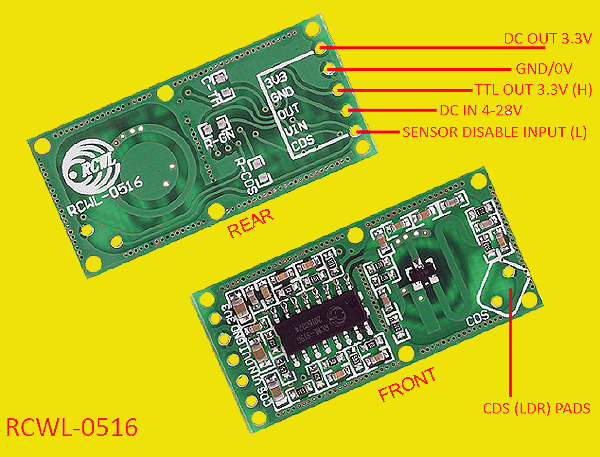
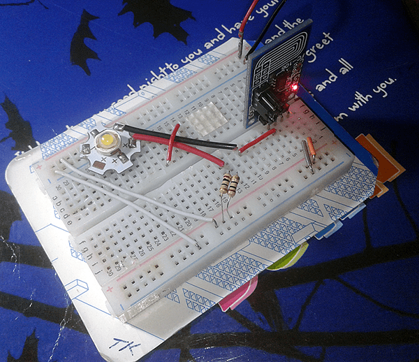
Presented here is an automatic motion sensor switch built around a cheap ‘Doppler Microwave Radar Sensor’ that can be easily used as standalone detection sensor. The circuit, designed as an alternative to the common PIR motion detectors, is perfect for DIY microwave motion sensor light switch, human sensor alarms, smart security devices, etc. The given circuit offers a detection sensitivity of about 7 meters, and when triggered its switch remains in the active state for around 3 seconds before returning to the idle state. At the heart of this affordable idea is the RCWL-0516 microwave radar motion sensor module.
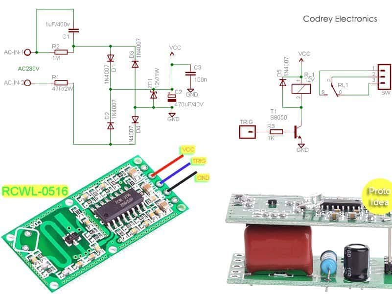
The schematic shown next is infact a perfect blend of an AC230V power supply unit and a DC12V electromagnetic relay driver realized with the help of some generally available inexpensive components, in addition to the aforesaid microwave radar module. The whole circuit can be assembled on a small piece of veroboard/customized printed circuit board to enclose in any convenient plastic container. Keep in mind that the circuit always carries fatal high-voltages, so extreme care must be taken to ensure that unisolated section of the electronics should be kept insulated from the outside world!
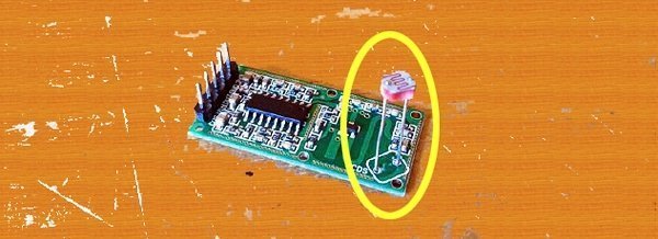
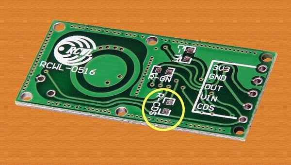
It is good, especially corridor lighting, to have a light sensor (CDS Sensor/LDR) attached with the motion-sensing sensor, since it ensures that even if some movement is detected, the switch will only be activated when there is little light or zero light. Here, you can solder a 5mm LDR on the 2-pin solder pad tagged as CDS.
If you are adding the light sensor, note that by adding a resistor (in parallel with the internal 1M ohm resistor, marked as R-CDS) it’s possible to change the light detection threshold as per individual requirement. A 47K-100K resistor in parallel with that 1M resistor will work fine with standard 5mm LDRs.
As you might noticed, the 12V electromagnetic relay (RL1) in the circuit is driven by an S8050 transistor (T1). If desired, you can also use other relays with a different supply voltage rating (5V for instance). However, in that case, the power supply configuration (now 12V) will have to be changed, of course with some other modifications.
Please provide circuit with 5vdc
@Ajay Puro: Noted, Thanks!
This is a dangerous power supply. When C1 is faulty the zener diode will be lit. There isn’t even a fuse in line.
It’s better to use a buck converter or anything with an transformer and a 78L12. Everything is safer than the provided scheme.
@Maatie: Most Chinese electronics designs now are based on capacitive topologies because they are more compact and economical. Further, my prototype is working safely since last 90 days. In the circuit, you can find an inrush current limiter (R1), and a 1uF/400V “CBB22” type capacitor (specifically designed for AC applications and meet the safety requirements of various safety standards) as the key component.
See, the Polypropylene film has superior electrical characteristics.
the Polypropylene film features very low dielectric losses, a high insulation
resistance, a low dielectric absorption, and a very high dielectric strength. Further, the capacitor has a flame retardant red epoxy resin seal. Further, in my experience, the most common (usually but not always) failure mode of a zener diode is short circuit. In short, nothing to fear more about safety issues!
Obviously you’re free to try any better 12V power supply unit in lieu, like the compact 12V smps module from HLK (https://www.rhydolabz.com/miscellaneous-miscellaneous-c-205_82/12v-5w-smps-module-hilink-p-2291.html), Anyway, I still not prefer a beefy step-down transformer in this circuit.
Can someone tell me that is it possible that switching of relay may trigger sensor as false detection because i am facing this issue when i am keeping sensor too close to relay
I was hoping to find a circuit to find timber studs in a wall cladded with plaster board, using a radar module. I have had many stud finders over the years and they never work accurately. I always have to drill a hole to make sure. I have even bought a Flir sensor phone, but it was not good enough. What do you recommend?
@Lance Christiansen: As you’re aware, detecting wood with electronics is a bit complex task. Materials like wood are very poor electrical conductors. A commercial wood stud finder works by sensing density changes inside walls.
What I learned so far is that a thermal camera/imager can’t see through walls! However, if we point a thermal camera at a wall, it will detect heat from the wall, and if something inside the wall causes enough of a temperature difference, the imager will be able to sense it on the surface of the wall. This doesn’t make much sense here.
You can of course try the impulse radar idea (transmitting raw signals to classify different wall types as well as the material behind the walls) if you’re ready to rig up one device yourself. But what I am thinking of is the new design of an electronic timber stud detector able to “see through walls”, it might take sometime to complete, though.
I apologize for my limited knowledge on this subject. Thanks!