Having a moderate presence of scorpions in my locality, I recently bought a cheap ultraviolet (UV) flashlight in the hope of swaying them to move elsewhere. It’s because, a while ago I noticed that when I use a common white light scorpion seem less disturbed, but when exposed to ultraviolet light (from my counterfeit currency detector torch) they got annoyed and try to run away from the spot!
About scorpion spotting
Scorpions are generally nocturnal creatures prefer to be active during the night looking for food and mates. Scorpions are predacious by nature and feed on a wide array of insects. Since scorpions love to reside where it is moist they present a hazard both in the yard and in the home. Note that irrigated lawns and landscaping will naturally attract them.
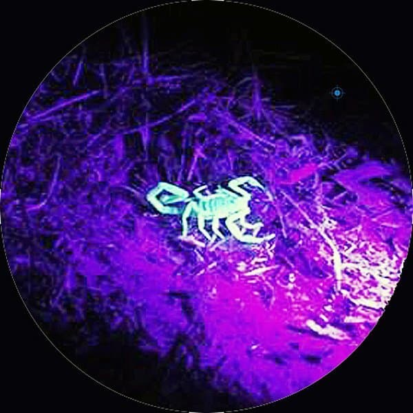
It is very difficult to see scorpions during the day, but at night it is another story. Ultraviolet light from a black torch that hits scorpions gets converted by proteins in their exoskeletons into light of a blue hue i.e. an eerie greenish glow is then visible to the human eye. With powerful ultraviolet light, small species can be seen from many meters away in dark nights.
My scorpion detector
Quite naturally, sometime after playing with the aforesaid Chinese ‘black light’ toy, I decided to fabricate my own version of a portable ultraviolet scorpion detector using generally available inexpensive components. The basic idea is pretty simple and useful for certain other applications too (you can use ultraviolet light for detecting urine stain on carpets/curtains/furniture fabrics that’s otherwise invisible to the human eye).
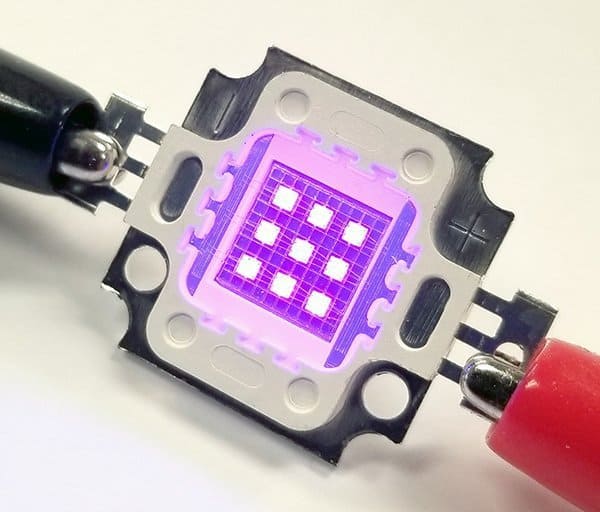
Other day, I logged onto my Amazon account and ordered a pair of 10W ultraviolet LEDs (395nm) and heatsinks. But when come back after the rush, I quickly realized that those 10W UV LEDs need comparatively higher dc voltage and current, hence not a good fit for my current scheme. So, after some quick tests, I packed them safely and laid aside for future use.
Since the head of my Chinese UV torch has a cluster of nine 5mm UV LEDs, I decided to follow that idea but with more number of UV LEDs. So I placed another order for an offer pack of fifty 5mm UV LEDs (935nm).
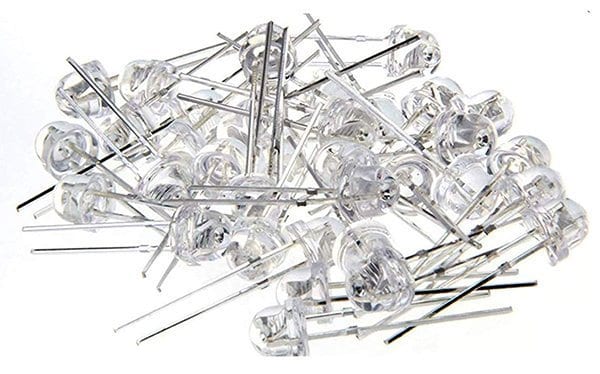
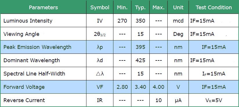
See the key specs of those UV LEDs I bought from Amazon:
Since I owned a bunch of small UV LEDs I decided that I could simplify the overall design of the scorpion detector by using a standard lithium-ion battery for the power source. At first, I grouped twelve UV LEDs in a rectangle and made sure that the LED cluster worked well with the output provided by the 1S Li-ion battery (3.7V – 4.2V). A current limiter series resistor was also chosen empirically so that the worst-case operating current lies within the recommended range. WARNING! The UV LED cluster is capable of producing harmful ultraviolet radiation. The eye’s protection reflexes might not work at 395nm wavelength, and thus cause panoptic damage if exposed to direct or specular ultraviolet illumination.
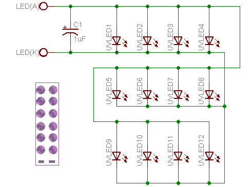
As mentioned above, power source of the UV LED cluster is a single-cell (1S) lithium-ion (Li-ion) battery. My first pick was a 3.7V/1200mAh (18650 type) unbranded Li-ion battery as it’s the only one ready to hand at that time. Since total current consumption of the UV LED cluster is about 180mA, I used a 1.6Ω/500mW resistor as its current limiter (leeway admitted).
You may want a tighter beam from your UV scorpion detector, and think about using one of the lens & reflectors made for LED emergency lights. Take note that those optical accessories are appropriate only for visible light, and don’t work with ultraviolet light.
The lithium-ion part is really an old one once I lifted from a defunct solar garden light. Since it does not have internal protection, I opted for the improved version of the quite popular (and extremely cheap) TP4056 charger module.
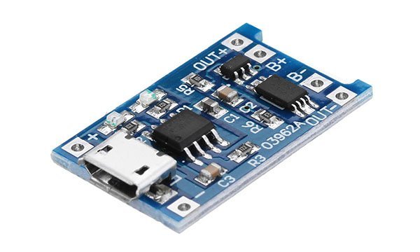
The USB/5VDC input ‘pro’ module based on TP4056 (or TC4056) has two additional chips onboard to ensure enough protection – DW01A and FS8205A.This particular module is pre-wired to handle 1000mA charging current, we can alter it from 200mA to 1000mA simply by changing the value of a single resistor (R3), though. Below you can see the module’s circuit diagram, borrowed from web.
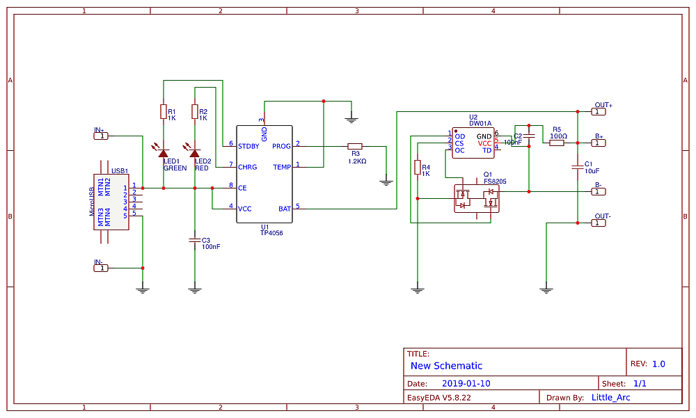
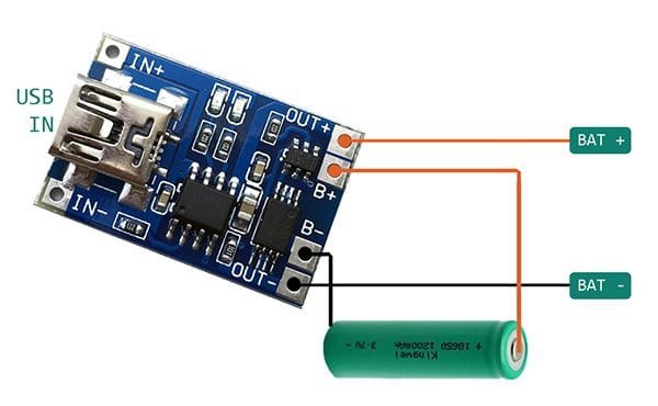
This is the electrical connection diagram for the battery charger plus battery setup. It’s simple, straight forward, and hardly needs an explanation. Just follow the route, that’s all needed!
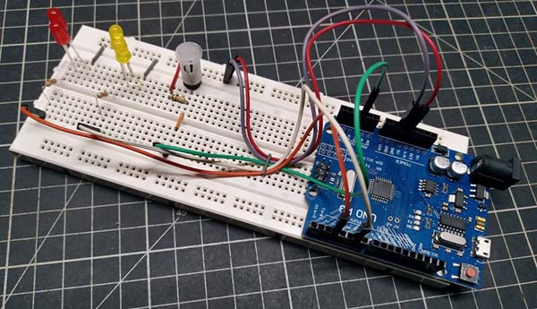
Now to the complete schematic of the ultraviolet scorpion detector (see below).Use a small piece of predrilled circuit board with some copper traces to prepare the UV LED head. Rest of the construction barely requires a circuit board – simply put it in a point-to-point wiring style. And then, house the entire assembly in a small rectangular plastic enclosure. For handheld operation, bolt a plastic handgrip onto the top of the enclosure.
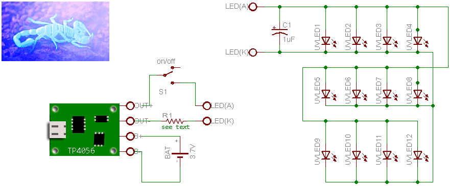
With the ultraviolet light head showed here (12 x UV LEDs) – current limited by a 1Ω resistor – I was able to get a living scorpion gleam from one meter distance in a subjective outdoor testing. Apparently, more sophisticated electronics circuits might be devised to make luxurious/feature-rich/powerful scorpion detector spotlights, but they probably offer comparatively little additional benefit for the intentions of episodic scorpion detection, I guess. Moreover, I have no idea how powerful the ‘black light’ in such a high-end scorpion detector flashlight is, and I don’t have an in-depth knowledge in scorpiology. I’m not ashamed to admit that!
A troubling thought – TP4056
TP4056 is a very small module uses the TP4056 controller. Its default configuration is for 1A charge current. This charger module has a good CC/CV profile and can be adapted for many different Li-ion/LiPo charge configurations, and comes with two status indicators for charging (red) in progress and charging complete (blue).There are two types of common TP4056 modules – one with only the charger chip on board, and the other with two more chips for onboard battery protection. Somebody might think what happens if the battery was connected backward. Based on my personal experience, I can notify that it gives smoke and finally a dead charger module.
However, today’s TP4056 modules cannot be relied upon to work correctly and safely. Although they’re following the original scheme, the TP4056 chip has itself been cloned, and some of them do not terminate the charging process at the right voltage. Even if the connected battery has a relatively low capacity, it would still be dangerous in such situations.
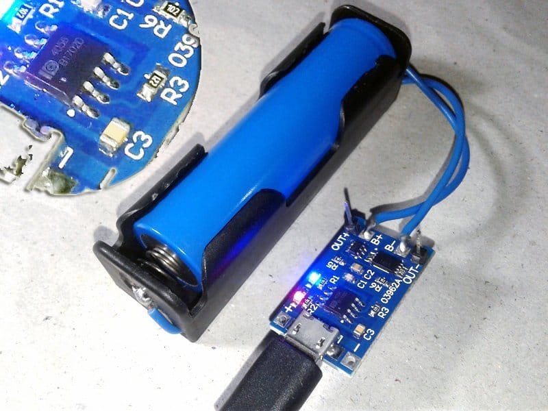
I got a couple of cheap TP4056 modules again from China, but this time built with a knockoff of the NanJing Top Power ASIC TP4056. I’ve seen that the clone chip is plainly marked as 4056 but with a squished logo. If you’ve got one of these forgery modules, you can find that both indicators remain lit during the middle of the charging process (see above photograph). The charging process never stops, especially with a trifle weak/aged battery – a possibly dangerous process!
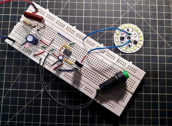
Coming back to the project, this is the crude photograph of my get-go mock up. I have plans to make a dedicated PCB and a 3D printed enclosure later on. Perhaps I will make a modified model with more UV LEDs and some other cool features.
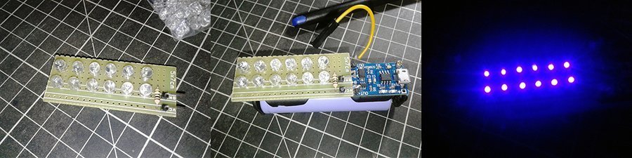
Here, the 1uF capacitor in the UV LED circuit board is soldered underneath, and a wire jumper is used instead of the on/off switch. Note that the UV LEDs get quite hot when burning, so a brief operation is recommended. Also try to keep the soldering time of UV LEDs as short as possible as they’re highly sensitive to heat (and static charge).
Postscript
- Now you can purchase pretty great 10W UV LEDs for your next level ultraviolet light projects from Banggood (https://www.banggood.in/10W-UV-Purple-LED-COB-Bead-Light-High-Power-Ultraviolet-DIY-Lamp-Chip-p-1155898.html)
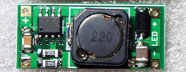
With the below pictured XL6003 module, a 1S Li-ion battery (3.7V) can be used drive two to three 1W LEDs connected in series, two to five 500mW LEDs connected in series. The default constant current drive output is 650mA, tailored for a 1W LED. This constant current drive level can however be adjusted by altering the value of the current sensing resistor onboard (https://www.aliexpress.com/item/32918936790.html)
Adding a lens to your device would cast the beam out further without having to change the circuit. Adding 2 lenses would allow you to adjust the beam wider (dissipating the light) or narrower (intensifying the UV light).
M.Hummel: As observed by me, the ordinary lens and reflectors don’t work with UV light. That’s why I ordered a bunch of “blacklight” lens & reflector kit from Bangood but didn’t get it yet perhaps because of the India Lock down. Since those parts are for rounded UV light heads, I’ll need to reform my existing UV light head. I’ll post the photo of my final build hereafter. Thanks for your insights!