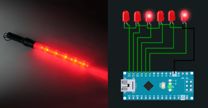
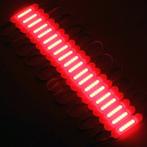
I recently got my hands on a string of COB LED modules with lens for a big project – smart driveway marker. I’m still tweaking things but I’m planning to share the project soon enough.
Apart from those red COB LED strings, I also bought a cheapo assortment of purple COB LED strings, and used one of them in another little project – the Arduino Build Light Indicator!
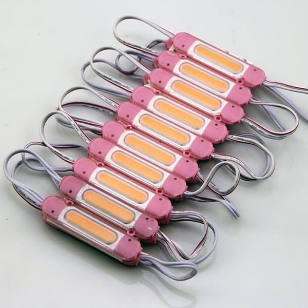
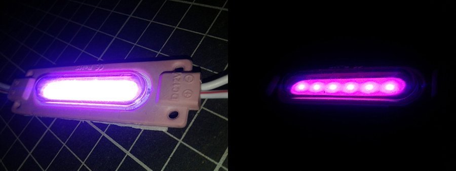
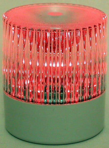
Generally, total 20 COB LED modules are cascaded in one string, and each module has 6 chip LEDs inside (under the lens). Since the COB LED modules can easily be cut on the given cut points to use as standalone 12V COB LED modules with pigtails, I tried just one pink COB LED module in my quick project. Also, I wanted the experiment to be more about learning something new and not preparing a complex artifact. The single pink COB LED module draws about 130mA of current at 12VDC.
This quick tutorial will show how to build your own Arduino Build Light Indicator. Let’s first talk about the build light indicator and then build it physically.
What’s a build light indicator?
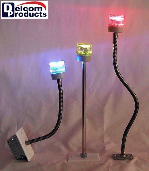
As found in the Wikiwand page (https://www.wikiwand.com/en/Build_light_indicator), build light indicator is a simple visual indicator used in Agile software development to inform a team of software developers about the current status of their project. The actual object used can vary from a pressure gauge to a lava lamp, but its purpose remains the same, that is to say, to quickly communicate whether a software process (such as a ‘build’) is successful or not.
Arduino inside build light indicator
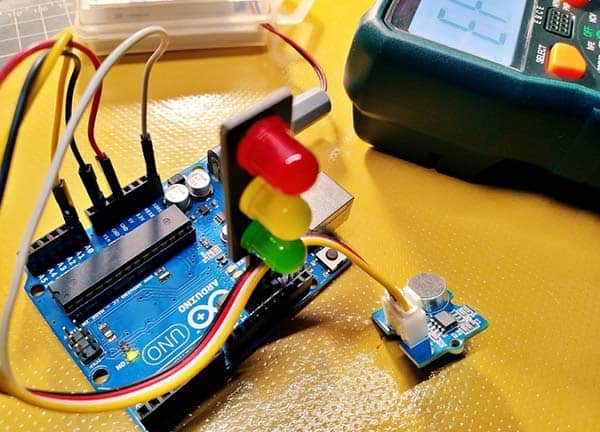
Frankly, I’m naming this project “build light indicator” simply because it’s a warning/signal light set up which can be placed in a noticeable location to let others know when it’s okay or not to disturb you. In this project the build light indicator can be on and off by keyboard input, that is simply a decimal (or character) input.
The Arduino sketch, to implement a command menu using the Serial Monitor of the Arduino IDE, is pretty simple – listen on serial, if receives a 1,then set D13 HIGH, if receives a 0, set D13 LOW. This sketch intentionally use the D13 pin as there is an onboard LED driven by D13 that will serve as a quick status indicator here. However, there is also an extra power LED driver circuitry which will be described later. That’s all there is to it. Let’s see the Arduino sketch.
void setup() {
Serial.begin(9600);
while (!Serial) {
;
}

Serial.println("System Ready! Enter 1 to ON & 0 to OFF");
pinMode(13, OUTPUT);

}

void loop() {
if(Serial.available())
{
char input = Serial.read();
if(input == '0'){
digitalWrite(13, LOW);
Serial.println("Turning OFF alert");
}
else if(input == '1') {
digitalWrite(13, HIGH);
Serial.println("Turning ON alert");
}
else {
Serial.println("Invalid Command! Enter 1 to ON & 0 to OFF");
}
}
}
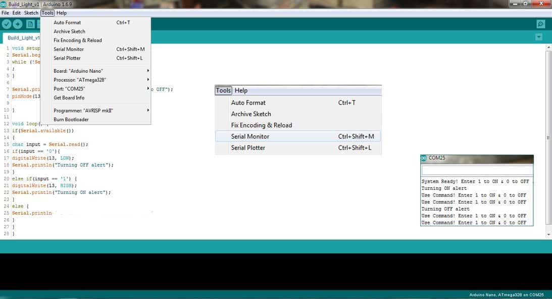
Now open this code in your Arduino IDE and upload it to your Arduino Nano. As you are aware, in Arduino Nano boards, the serial connection can be made either via USB port or by digital pins 0 (RX) and 1 (TX). The Arduino IDE includes a serial monitor, a built-in terminal to communicate with the Arduino board. You can open the serial monitor by keyboard shortcut “Ctrl+Shift+M” or through menu “Tools » Serial Monitor”.
Now to the driver circuit for the external LED (the actual build light indicator). The COB LED module was rated at 12VDC, so I wanted to run it off 12VDC to get maximum light output. I could use a relay to switch the LED, but it seemed like overkill, so I looked into my parts drawer and landed up with an alternative plan. Okay, see my random idea shown below. Sorry, I couldn’t get shots of my breadboarded test setup…
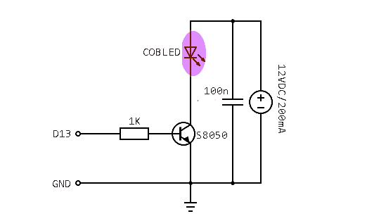
The driver transistor used here is S8050 which is a BJT rated to 20V and 700mA. This is the quick test report of the S8050 transistor used in my test setup:
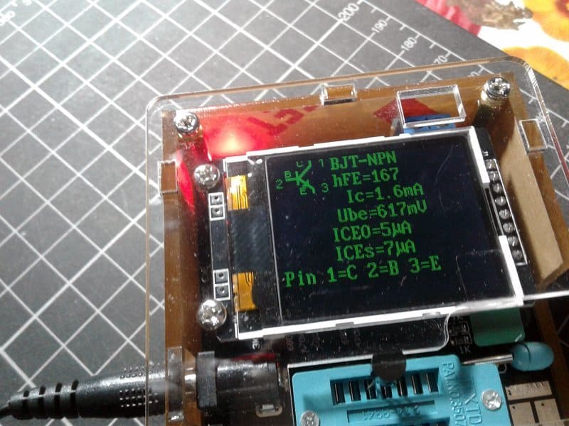
When it comes to understanding collector current (Ic) in BJT beta (β) variations, I’m not going to reproduce the entire theory, but let’s not forget about hFE and hfe abbreviations which are equivalent to βDC and βAC, respectively. You may have noticed that BJT datasheets readily provide detailed data on the β–Ic relationship, and there are diverse betas to choose from. You might find this a bit confusing!
The following snip is from the official datasheet of S8050 BJT, published by UTC. There you can also see the relationship between beta and collector current.
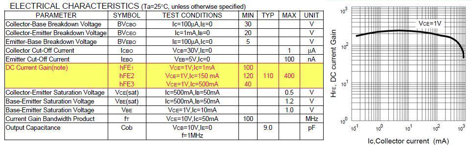
In principle, β decreases at the higher end of the Ic range. Also, all of the hFE–Ic plots have different curves for different temperatures. This warns us that beta is influenced not only by collector current but also by temperature (not very significant in a general-purpose application, though). Anyway, if you’re concerned about how these changes will alter a circuit’s behavior, you might have to do some experimentation.
Back to the build, finally, remember to put Arduino, LED driver circuit, 12V power supply unit, and the LED into a nifty translucent enclosure. See the rough modeling idea given below.
Great… you just owned a splendid build light indicator, powered by an external AC-DC adapter and controlled via the USB interface!
By the way, if you dislike the inclusion of the additional 12VDC adapter, and want to stick with the USB power only, you can then employ a little DC-DC boost converter module (see below) to raise the available USB 5VDC to 12VDC. But I’m guessing these cheapo versions may need extra external smoothing components, time will tell.
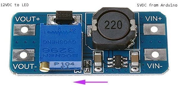
However, if you are unlucky enough to have a USB port with unusually weak output, you have probably found the above solution unworkable. And, if the overall setup might draw more than 500 mA it will overload/kill the USB. Beware!
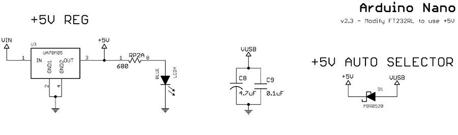
As an aside, having Arduino Nano connected to an external power source via barrel jack and to computer via USB cable simultaneously is normal, indeed de rigeuer for most. The Arduino Nano has Schottky backflow guard diode between USB power and 5, and runs on ~4.6volt when powered from USB. So, when using both power supplies at the same time, the Arduino Nano will simply swap to the preferred power supply. Usually, external 5V on the 5V pin (>4.6volt), or >=6.6V on the Vin/Raw pin will have priority over USB power. This simply means that USB power supply will be cut off and the external power source will power the Arduino Nano.
Let’s go further
As might be expected, there’re several ways to control your build light comfortably getting the same output. The Arduino-Visual Basic integration is certainly an effective idea. Arduino-Python integration is another one for a good try. Further, it should be fairly simple to change the setup to work with Bluetooth or Wi-Fi.
- Visual Basic https://www.electroschematics.com/arduino-visual-basic-integration/
- PHP heidislab.com/tutorials/how-to-communicate-with-an-arduino-via-serial-using-php-code
I hope that this short primer on build light indicator has helped you getting off the ground with your own ideas. If you have any additional insights that you would like to share, feel free to make your contribution in the comments section below.