Here you can find the project details of a simple and low-cost pull-pin security alarm. While travelling, rig the alarm unit to your luggage using the alarm security cable. If so, when somebody tries remove the security cable loop to steal the luggage, the internal circuitry immediately detects it and raises a noticeable audio-visual alert.
The pull-pin alarm can also be used as an economical monitoring device to signal medical staff that a patient is about to stand. Its operation is simple there. When the patient begins to get out of bed, since the alligator clip of the security cable is attached to the patient’s clothing, the security cable naturally stretches and removes the pull-pin and thus enabling the alarm.
Simply put, you will receive a startling alarm when the security cable/pull-pin is removed from the alarm box. Okay, let’s get started!
Oh, I almost forgot it … this is a link to my basic pull-pin alarm project, which was printed over a decade ago https://www.electronicsforu.com/electronics-projects/pull-pin-security-alarm (Thanks to EFY).
Below you can see the schematic of the Arduino Pro-Mini-based Pull-Pin Security Alarm.
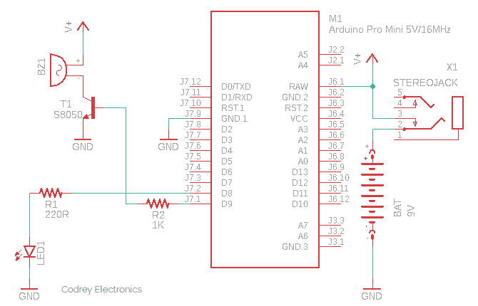
In this setup, a 3.5mm stereo headphone jack is used as a tricky power on/off switch to enable/disable the alarm operation. The circuitry is configured in a way that, the alarm gets activated only when a 3.5mm TRS stereo audio plug is removed from the audio jack X1. Since a regular 3.5mm stereo headphone jack can handle 1A of current at 12V (maximum), we can use it as a little power on/off switch as utilized here.
The 3.5mm stereo audio plug does not play any “electrical role” here. That being said, you can tie it at the end of a security rope, or solder a long thick wire to it to form a tailor-made security cable.

Although 9V battery operation is indicated in the schematic, you can use a 2S Li-ion (or LiPo) battery there (7.4V nominal – 8.4V maximum) as the power source. At 9VDC, the system might need a peak current close to 200mA in active state (as I observed).
Let’s take a look at the list of components we need.
- Arduino Pro Mini 5V/16MHz x1
- S8050 NPN Transistor x1
- 16Ω Magnetic Buzzer 5V-12V x1
- 5mm LED x1
- 5mm TRS Stereo Audio Jack and Plug x1
- 220Ω ¼ w Resistor x1
- 1KΩ ¼ w Resistor x 1
- Battery 7.4V-9V x1

Here’s the simple code you can try right now. Upload this code to your Pro Mini through your favorite USB-to-Serial Adapter. I now use the FTDI Basic Breakout (5V) but there’re others you can try.
void setup() {
  pinMode(8, OUTPUT); // LED
  pinMode(9, OUTPUT); // Sounder
  lightOn();
  delay(3000); // Turn-On Delay
}

void lightOn() {
  digitalWrite(8, HIGH);
}

void playMelody() {
  tone(9, 1100, 100);
  delay(1000);
  tone(9, 1319, 400);
  delay(1000);
}

void loop() {
  playMelody();
}
This crude code is prepared to turn on the LED (D8) instantly when powered up and to start the sounder (D9) after a short delay of 3 seconds. However, it’s pretty flexible, so anyone can tweak it as they like.
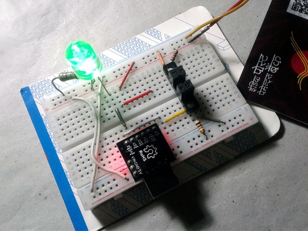
When it comes to my breadboard build, oh, it’s a little dirty, but it worked as expected!
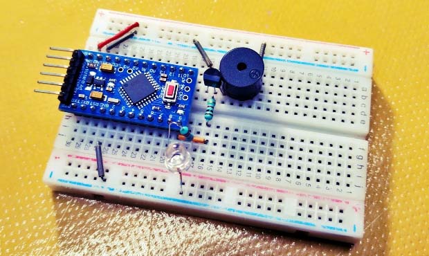
See a live shot below (I used a 5mm water clear Blue LED).

A durable plastic enclosure is an economical way to protect this electronic device from any adverse effects, and it’s very crucial because this is a portable security device. A small soapbox-style enclosure will give your pull-pin alarm prototype a professional look. You can also use the shell of the abandoned security alarm device, or choose a similar box that allows you to include your entire build. The images below are for example purposes only.

That’s all for now. If you’ve any questions about any of the projects you see here, don’t hesitate to contact me. All feedback is welcome!