I’m sure there’re a lot of electronic gadgets in your house that can be recycled. The good news is most of them can be used again or for another purpose. So, don’t just throw those gadgets in the garbage. You just have to take some time to do a little research!
As an example, if you’ve an unused Goodknight Gold Flash system taking up space in your messy drawer, note that you may be able to repurpose it for some other funny practical applications. Let me show you how…
For those who’re not familiar with the Goodknight Gold Flash system, it’s a quite popular electric liquid vaporizer with flash action and an intelligent heater control system. The heater controller of this mosquito repellent is the fact an unidentified microcontroller-based minuscule electronic circuitry.
This AC230V device has two operating modes – Normal mode and Flash mode. On flash mode, it discharges flash vapours for thirty minutes every four hours and then automatically flips back to normal mode. Green light from a bicolor LED indicator shows the normal mode while yellow/amber color announces the flash mode.
See https://www.goodknight.in/products/indoor-electric/goodknight-gold-flash-system/
So, we’ve an awesome electric mosquito repellent that’s begging to be hacked!
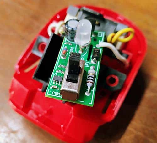
First, carefully dismantle the device into its key components. Unscrew the enclosure to separate it into two parts (no need to further disassemble any components at this time).
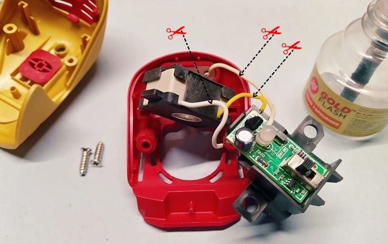
Now you’ll need to cut/desolder three wires (two white wires and one yellow wire) coming from the PTC heater element to the PCB to take the printed circuit board out.
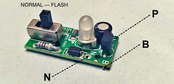
There’re three key circuit points in the PCB labeled as P, N, and B. Now it’s worthy to note down the Normal and Flash mode positions of the slide switch as well.
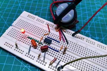
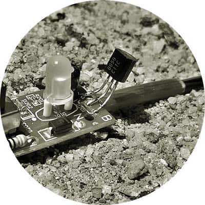
Next thing to do is to replace the BT169D thyristor in the PCB with an S8050 transistor.
To do that, simply desolder the BT169D thyristor, lift it off, and gently solder the new S8050 transistor there while keeping the same orientation (label side facing inwards). Soldering scares some novices, but it’s a great art and will make the whole mod easier!
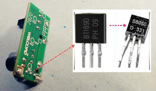
See my quick and dirty attempt below.
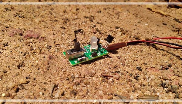
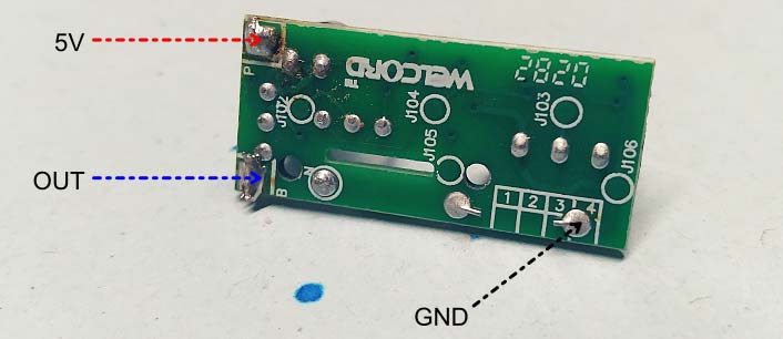
Now solder some low voltage wires onto the circuit points P, B, and the common GND point (Just ignore N) as depicted below. Leave the wires long, as you can trim them to size later on. The P point is for 5VDC input, GND is the common ground (0V), and the B point is the open-collector output (OUT).
Note that this modified PCB will work happily from 3V to 5V dc input but a 5VDC power source is recommended for optimal performance. The overall current consumption is surprisingly small to consider (< 5mA).
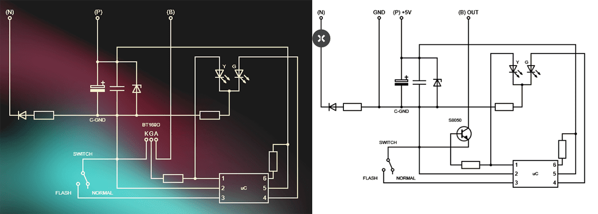
Seriously, if you slip somewhere, you’ll brick the microcontroller. So, I prepared a couple of rough schematics of the Goodknight Gold Flash system (only for your learning purposes). Look, on the left is the original schematic that uses BT169D, and the modified version with S8050 is on the right. Oh, well, this might help you see where things go!
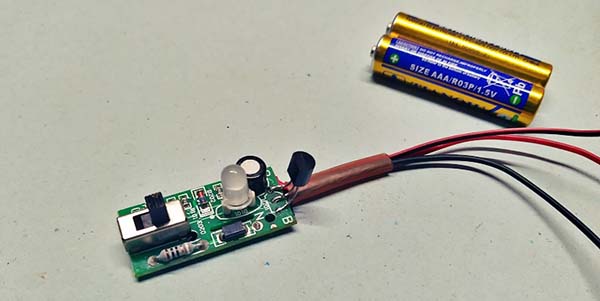
Below you’ll see my modded circuit board (not beauteous but it works).
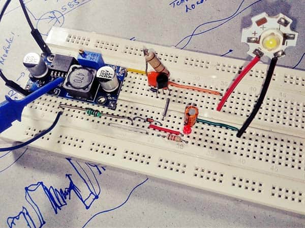
Okay, it’s time to make a preflight test of the modded setup. So, start by powering it with a regulated 5VDC power source but after putting the slide switch to its OFF (normal) mode. Before that, try to put a 100Ω ¼ W resistor in series with the positive rail.
Promptly you can see that the bicolor LED starts flashing in yellow color two times and then stays in green color.
Then, move the slide switch to its ON (flash) mode. Now you can see a yellow flash three times followed by a steady yellow glow. At this time, the output (OUT) is in active state which lasts for 30 minutes, and it wakes up again after 4 hours in a rigidly accurate cyclic manner.
Well, the initial test was completed successfully. Hooray!
Apologies if the above instructions seem a little anemic, but there isn’t really much to head you through this time.
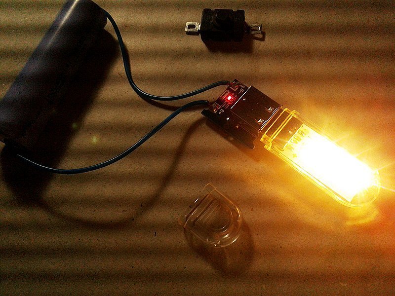
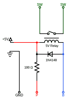
You can now utilize the modded setup to control external things with very little effort. This can be done easily by wiring a low-current (< 50mA) 5VDC electromagnetic (or solid-state) relay between the 5V (P) and OUT (B) connection spots (see below). It’s not the best approach, but the easiest.
So now you’ve hacked your electric liquid vaporizer circuitry, it’s time to give it a real-life test run. Personally, I’m using my modded circuit board to control small heat lamps installed in a barn.
It should go without saying, but you still need to remember that there’re so many distinct ways to repurpose this nifty bit of electronics. In case of ample demands from my beloved readers, I’ll try to share more fantastic tips and tricks at some eventual time in the future.
At the end of the day, choosing how to go farther with this crude idea is a decision you’ve to make based on your needs and preferences. Anyway, I hope you’ve had as much fun reading this post as I had writing it. See you next week!