Taser™ is a weapon that fires wires to deliver a temporarily paralyzing electric shock used in many countries and by law enforcement agents. Certainly my intention is not to share the circuit diagram of a do-it-yourself Taser™, but a funny idea help you to build your own model of a simple electric shock gun – the Nano Taser. Well, get ready to start building the miniature of your self-defense weapon that fires electrodes to shock and debilitate attackers!
Circuit Description
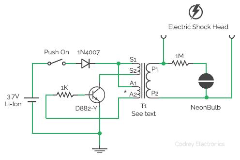
Here, a blocking oscillator is made using D882-Y n-p-n transistor, a fixed resistor 1K, and a small high-frequency transformer (smps transformer from a cheap smps circuit board). The blocking oscillator is a feedback oscillator type which produces relaxation oscillation. Basically, the self-stroking/positive-feedback oscillator circuit works by rapidly switching the transistor to output a dc type pulse.
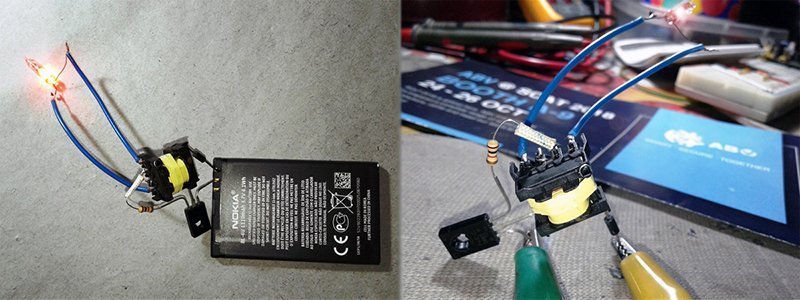
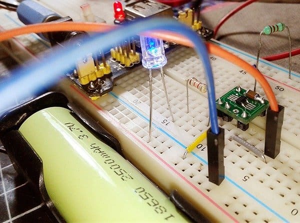
The circuit is designed to operate from a single-cell lithium-ion (1S Li-Ion) battery. You an use the common 18650 type (or a 3.7V Li-Ion mobile phone battery) with at least 1000mAh capacity. An important thing to note down is that the circuit is only for momentary operation because a continuous mode of operation will kill the transistor even if it has a heavy heatsink. A push type (push-on) button switch is selected as the trigger switch on account of this inherent drawback.
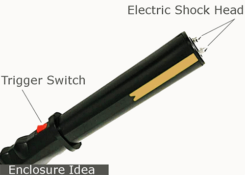
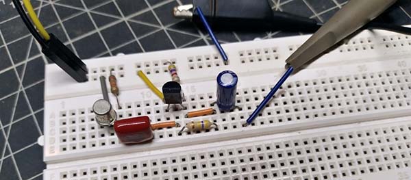
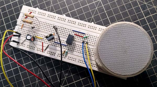
A bit of perforated circuit board is suggested for construction of the whole electronics, but you can use point-to-point wiring method (dead-bug style) if in demand. Anyhow, try to retain all interconnections as short as possible, as usual with all high-frequency circuits. The neon bulb works as a high-voltage indicator cum minimal output load for the transformer. Based on the type of transformer used, value of its limiter resistor may need revision If so, pick a resistor in 100K to 1M range by trial and error. Output wires of the transformer T1 should be connected to the electric shock head – made with two closely spaced conductive pads/metal rivets/ thumbtacks (see enclosure idea).
Transformer Trick
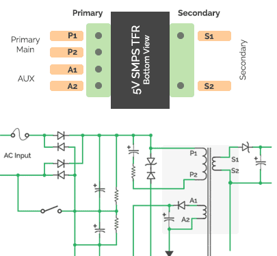
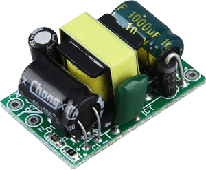
As told, an smps transformer (aka chopper transformer) is the core part of the circuit but it’s very hard to wind such a one at home. A proven trickery is the use of a readymade one lifted from any cheap 5V smps adapter – the mobile/usb charger for example. Before removing mps transformer from the circuit board of the smps adapter, go through its pcb tracks to identify the original primary, auxiliary, and secondary coils of the transformer. Following figure will help you in probing this quickly. Take note, in this circuit we’re going to use the transformer’s original primary coil as our secondary coil, and vice versa. Here’s the rough pin data of my smps transformer (removed from a partially-defunct Nokia 5V mobile phone charger):
- Primary (P1-P2): 7.6 Ω
- Auxiliary (A1-A2): 0.70 Ω
- Secondary (S1-S2): 0.2 Ω
Test Procedure
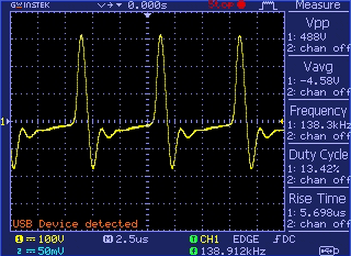
After construction, power up the circuit from a fully-charged Li-Ion battery, push and hold the trigger switch, and observe the neon lamp. Incase of zero/weak oscillation, recheck the wiring and swap the leads of auxiliary coil. Do not use your ordinary DMM to measure voltage at various points of the circuit as it might blot out your lovely digital multimeter. Even with a weak battery, I got a HV output around 500V p-p at 138 kHz frequency – see the (carelessly probed) random scope trace.
Is this a viable design?
Certainly not much! It has been just proved that the little circuit makes high voltage pulses many times bigger than its input voltage. This is caused by the inductor’s magnetic field as a response of fast current pulse feeds from the battery that is governed by the transistor. One thing should be considered seriously is that current dragged by the circuit from the battery is distressingly high. Moreover the number of turns on transformer (and its construction style) will affect the performance (positively or negatively) as well.
Next is from my workbench, filmed while I was experimenting with my dirty model:
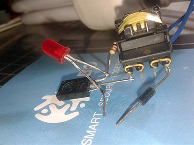
Later on, I found that one red-LED connected in antiparallel with the base and emitter leads of the transistor protects the transistor from accidental breakdown up to a considerable extent. Remember, anode of the red-LED should be wired to emitter of the transistor, and cathode to its base terminal. See next figure:
Driving AC230V CFL…
All over the YouTube, we find similar circuits used by many for lighting AC230V type CFLs from low-voltage battery packs. How is it possible to generate AC230V (with enough current demanded by the CFL) from such simple circuits? Sincerely I don’t know, but I too tried the given circuit (powered by a usb power bank) with one 11W CFL and it worked! Unbelievable?
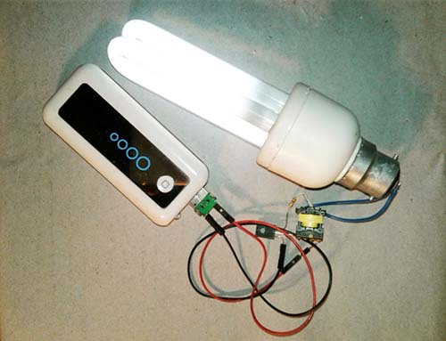
For the marvel trick, only part of the CFL you need is the fluorescent tubes and the wires that are connected to its filaments (circuit board inside the lamp base is not necessary so you can reuse it for something else). You can find two pairs of filament wires there. Connect one pair to one end of the output coil and the other pair to the other end of the output coil (the polarities don’t matter here). Done!
Great. I’ve done this project before. It doesn’t deliver much power, but it can cause burns on the skin if left for even as short as 3 seconds.🙂
Great work.
@Michael: Thank you, I’m happy to hear you feel that way!
BTW the design of a “mighty” Taser is in progress…