In this episode, you can see a simple yet reliable idea to build your own pulse drop detector circuit which is nothing but a configurable dual-monostable setup tailored for some distinct real-world applications. The given idea is really a multipurpose one, even a good fit for consumer and industrial electronics.
Circuit Diagram
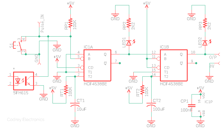
Let’s start with the pulse drop detector’s circuit diagram. As can see below, at the heart of the circuit is the popular dual, precision, retriggerable monostable HCF4538BE (IC1) runs on regulated 5 volt dc supply. The first monostable (IC1A) of IC1 is configured as a retriggerable monostable, and leading edge of its output is used to trigger the second monostable (IC1B) inside IC1. LED1 and LED2 are optional status indicators wired to the output of the first and second monostable, respectively. Push-on momentary switch (S1) is the test/trigger switch. Rest of the circuit details will be included later, in the bottom part of this article.
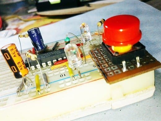
Test Process
After construction, power up the circuit from any 5 volt dc regulated power source, and push the test switch. You can see LED1 lights up for a while(~1s) and LED2 remains on for a comparatively long time (~10s). If you operate the test switch continuously in a rhythmic pattern, ie. exactly at one push per second or so, LED1 follows the switch action but LED2 stays on continuously until there’s no test switch operation. Thereafter LED2 also goes off after a time lag to signal the pulse drop at circuit input. That’s the end of the initial test!
Note down, RC components RT1and CT1 forms the RC time constant of IC1A whereas RT2 and CT2 works for IC1B. Formula for pulse width calculation is PWOUT = RC (PW in seconds, R in Ohms, C in Farads). The input pull-up resistor RP1 is essential here because the circuit input is configured in the main to process negative-going (falling) pulses only.
Real Life Scene
Now you’ve your own pulse drop detector (aka missed pulse detector) ready to handle low-going pulses at its input. If you want galvanic isolation, then add an appropriate opto-coupler (plus its input driver circuitry) at the input as indicated in the circuit diagram. Likewise, you can drive an n-p-n or p-n-p transistor to control external loads (an alarm, for example) by the pulse appears at the output (O/P). Keep in mind that a complementary output is available from pin 9 of IC1, as well. Okay, straight off to one real-world application situation of having to keep tabs on the rotation status of a reeling disc.
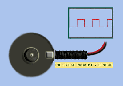
Literally it’s very easy with one optical slot sensor (https://www.sunrom.com/p/optical-slot-sensor), reflective infrared proximity sensor (https://www.amazon.in/VEEROBOT-Infrared-Proximity-Obstacle-Detecting/dp/B0115NCT4U), or inductive proximity sensor (https://robu.in/product/lj12a3-4-z-by-6-36v-dc-induction-proximity-sensor-switch-12mm/). But how to roll the little maths underneath?
Assume that rotation per minute (RPM) of the disc is 1500, and the rotation sensor mechanism is configured to output one pulse per rotation. Since the period (T) here is 40ms, with a 100n capacitor as CT1, we need a 400KΩ resistor (1MΩ trimpot in practice) as RT1 to ensure that the setup is compatible with the pulse input. The recommended duration of the second monostable should be about x10 that of the first monostable; this is reflected in the RT values- RT2=400KΩ & CT2 = 1uF (not very critical, it needs to be enough to extend the output pulse width). Got it?
This means that, when the disc starts spinning, IC1A is triggered which in turn triggers IC1B and therefore gives an output pulse through O/P. This state continues until the disc is spinning at the desired rate. In case the disc rotation failed (or slowed down fractionally), IC1A (IC1B too) no longer get the trigger pulse, therefore IC1B has no output pulse to deliver i.e. announces a pulse drop.
That’s all for now. If you spot mistakes, or believe I’m casually skipping over crucial points, please drop a message here!