This post explains how to build a mini PCB drill speed controller using a handful of common components you may already have stocked in your home lab. First off, let me say that this idea is based on an Arduino Nano microcontroller, which is intentional, because it may allow you to improve the basic build later without adding further costly components.
Well, let’s start our game with a simple Arduino Sketch!
void setup()

{
  pinMode(8, INPUT);
  pinMode(9, OUTPUT);
  digitalWrite(8, 1);
}

void loop() {

  while (digitalRead(8) == 0) {
    analogWrite(9, map(analogRead(A0), 0, 1023, 0, 255));
  }
  analogWrite(9, 0);
}
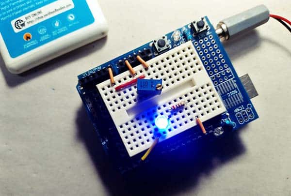
Now upload this code snippet to the Arduino board and setup your hardware as shown in the below wiring diagram. Note that Arduino’s D8-D9-A0 pins are used in this setup.
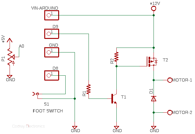
Power MOSFET is a great comrade to an Arduino microcontroller when it comes to driving a dc motor or another power-hungry device. However, finding a Power MOSFET that works well with an Arduino is a bit tricky, as most of the Power MOSFETs are not properly driven by the logic-level output (5V or 3.3V) of the Arduino’s I/O pin.
The easiest solution to this problem is to choose a logic-level Power MOSFET like IRLZ44 or IRL530 but another (something not very queer) approach is adopted in this design. So, just consider this as a learning exercise but go over the previous posts for more coherent explanations (you can find them in here somewhere).
Over and above, normally you could do a bunch of math to figure out the ideal gate pull-up resistor. In my case, I just used a 10KΩ resistor for R2 and all was good. Keep in mind, depending on your real requirements, you may need to fiddle with other components as well.
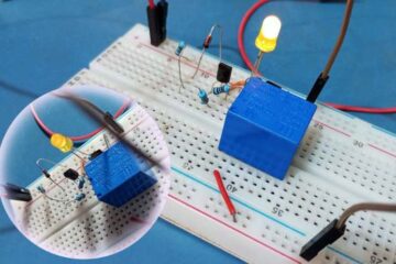
Finally, it often makes sense also to test your electronics before relying on it. So, once your prototype has been successfully built, do some preliminary tests to make sure everything is working as intended. In practice, you can use a small footswitch plugged into the audio jack to operate your mini PCB drill, while the potentiometer allows you to adjust the drill speed as required. Below you will find the inside view of a cheapo footswitch/foot pedal I used for this experiment.
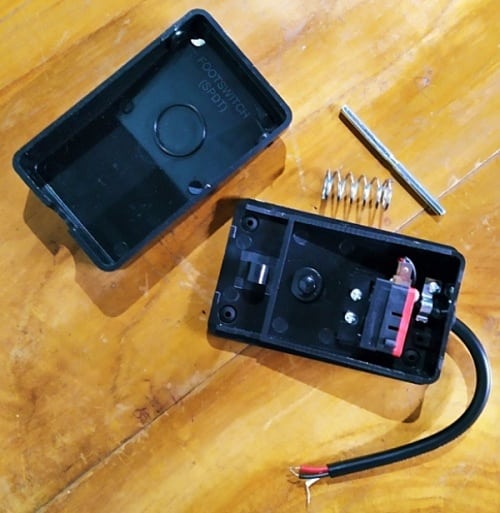
This footswitch actually has two sets of electrically conductive contacts. One pair of those contacts are classed as normally-open (NO) whereas the second pair of contacts are classed as normally-closed (NC). Remember that we need the normally-open (NO) contacts here!
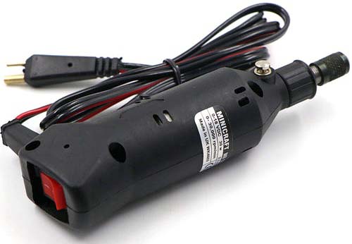
This simplistic drill speed controller works well with a hobby-grade mini PCB electric drill, so you can run the entire setup from its own 12VDC switch mode power supply.
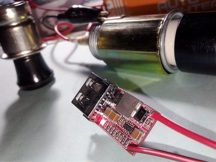
On another note, you can also make your own mini PCB electric drill using some of the cheaper parts that are usually available in most online stores. As you know, the key part needed is a small but powerful brushed DC motor.
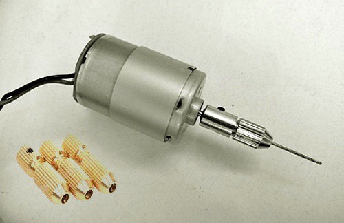
As far as I know the most common mini PCB drill motor is the RS-555-SH-4033 (https://s3-sa-east-1.amazonaws.com/robocore-lojavirtual/978/Motor-RS-555-SH_SA.pdf), but in my view, RS-380PH-4045 (https://product.mabuchi-motor.com/detail.html?id=99) or similar is a little better.
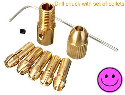
One thing to take into account at this time is the shaft diameter of the motor as it is very crucial when looking for a way to fix the drill bit to the motor. Based on the most popular types of small drill chucks, you should look for a motor with a shaft diameter of 2, 2.3, 3.175 or 5 millimetres.
First off, I just simulated the Arduino Sketch, but built a breadboard prototype later to test my idea in real world. Needless to say, it worked well as expected. There’s nothing fancy with that so I didn’t take pictures of it.
These are the parts I used in my Arduino Nano (v3) setup:
- T1: 2N2222A (https://www.onsemi.com/pdf/datasheet/p2n2222a-d.pdf)
- T2: IRF9540 (https://www.vishay.com/docs/91078/91078.pdf)
- D1: 1N4007
- P1: 10KΩ Potentiometer
- R1: 1KΩ ¼ W Resistor
- R2: 10KΩ ¼ W Resistor
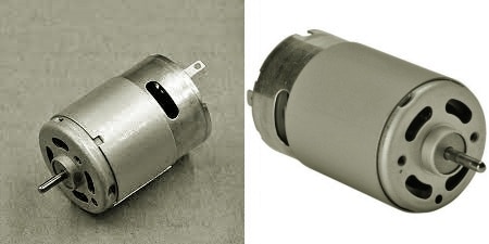
The drill motor used at that time was the ARS-550 brushed dc motor with a rated operating voltage of 8.4VDC, but I ran it with a 12VDC CCTV SMPS.
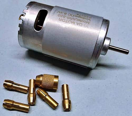
The no-load current (free current) consumption of this drill motor is around 350mA at 8.4VDC. Its stall current and RPM value have not yet been accurately measured. Sometimes I’m too lazy!
So, now you know how to build an expansible speed controller for a readymade or homemade mini PCB electric drill. The concept itself is pretty straightforward as the application is no challenge to any hobbyist. Good luck and let me know how it turns out for you. I’m happy to answer any queries or run further tryouts that I’m able to. Just leave me a comment below.
Finally, this post also uses photos from Google Images. I have edited some of them to ensure better clarity and compatibility. No copyright infringement is intended!