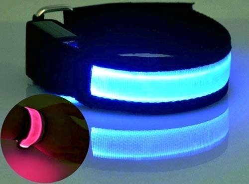
If you’re looking for the circuit of a running / jogging light up wristband, here’s a tried and tested design without a microcontroller. Even though the design presented here is based on traditional (leaded) components, it’s easy to replace most of them with surface mount (leadless) devices so that you can build an elegant running/jogging wristband that resembles a commercial gizmo!
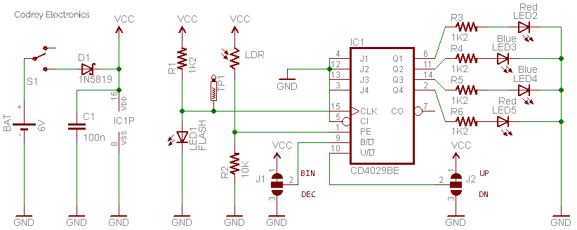
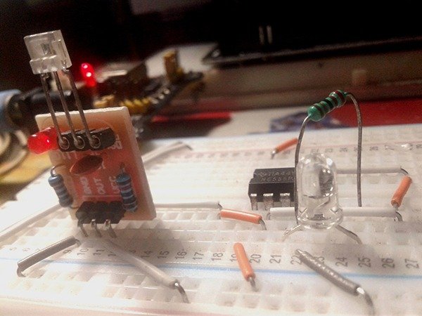
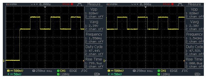
As can see in the schematic, the design is centered on an inexpensive and easily available CMOS presettable up/down counter IC – CD4027. The CD4027 consists of a four-stage binary or BCD-decade up/down counter with provisions for look-ahead carry in both counting modes. Internally the counter comprises a set of logic gates configured to implement the arithmetic addition operator. Normally the counter increments the 4 bit word (Q4,Q3,Q2,Q1) by one every time the clock input is toggled. Here, the required clock input signal is generated by a simple setup i.e. one flashing LED is used as the clock source, which is a high brightness 5mm LED when connected (through one current limiting resistor) automatically flashes between red and blue colors with an approximate flash frequency of 1.5Hz. See the oscilloscope display captured while it’s hooked to TP1 on initial power up.
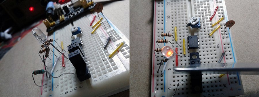
In this project, we will explore most capabilities of the 4029 counter chip which can count up or down, and in either binary or decimal mode. The up/down input (Pin 10) tells the counter to count up if it is a logic 1, or down when it is logic 0. Likewise, a logic 1 to the binary/decimal input (Pin 9) causes the counter to operate in binary mode, while a logic 0 switches it to decimal/decade counter mode. The four outputs (Pins 6-11-14-2) are used here to drive four LEDs where output 1 (Q1) represents the least significant bit (LSB), while output 4 (Q4) is the most significant bit (MSB). The preset enable (PE) input (Pin 1) of CD4029 allows the counter to be preset with a known value. When this input is logic 0, the counter operates normally but when it becomes logic 1, the logic signals present on the four jam inputs (Pins 4-12-3-13) get copied directly to the four bits of the counter. Here, a potential divider comprising an ordinary resistor and a light dependent resistor (LDR) is wired to the PE input to automatically lights up the output LEDs only when it’s moved off into the darkness. Now you can see the quick test video of author’s breadboard prototype powered by a regulated 5 volt DC supply connected between VCC and GND.
Note that, default configuration of the display mode jumpers runs the circuit as a binary up counter. However, you can reverse the jumper settings independently to set it in one of the four states i.e. binary up, binary down, decimal up, or decimal down modes. In the same manner you can detach the LDR from the circuit merely by lifting it off to disable the auto-on feature. When you have completed the experiment on a breadboard make sure power to your breadboard is turned off (it’s very easy with a breadboard to re-wire the circuit to try all sorts of variations). Next, remove all components and put them aside for future experiments (we’ll explore a number of practical applications in future articles). Finally move to the actual construction with SMD components on a customized SMD PCB that fits perfectly inside a wrist strap (see the model suggestion).
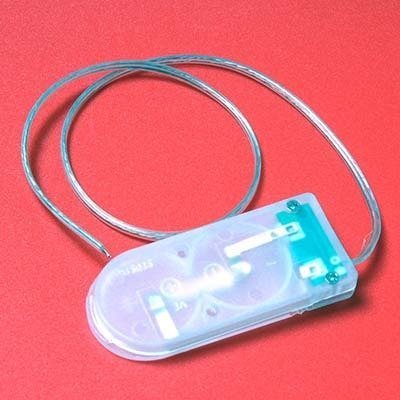
A tiny coin cell battery holder (CR2032-2) is seemingly ideal for this portable/wearable project as it can hold two 20-mm coin cells (2032 are the most popular size) in series to generate 6V nominal.
The internal circuitry of CD4029 is actually quite complex as it has a gating structure to count either up or down, in binary or decimal, and with parallel inputs to preset the count. All inputs and outputs of CD4029 are standard CMOS design, specified to operate accurately for clock signals up to 2 MHz minimum – typically 4 MHz, with a 5 volt power supply. There are of course newer logic families with the same functionality such as 74HC4029 as well. Below we’re giving relevant timing diagrams because it’s the easiest way to key out the operation of a digital chip like this one.
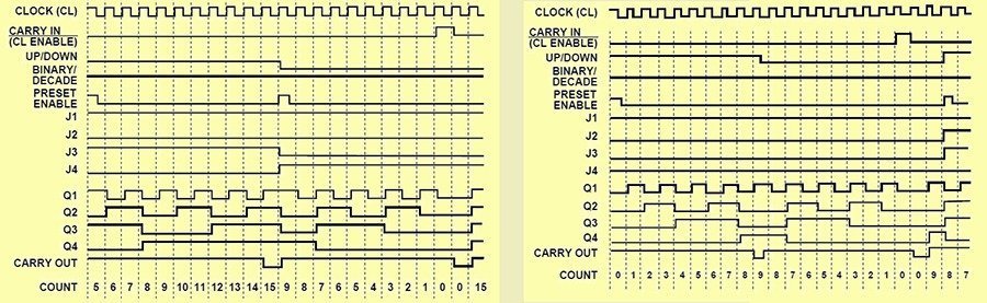
At the left of the display you can see the binary counter mode timing diagram. For each clock cycle the four bits cycle in a binary encoded sequence in this case starting at 5, counting up to 15 before being jammed to 9 and then counting down to zero and wrapping. Do refer the right of the display to learn how things work in decade counter mode. In short, binary counting is accomplished when the BINARY/DECADE input is high, and the counter counts in the decade mode when the BINARY/DECADE input is low. The counter counts up when the UP/DOWN input is high, and down when the UP/DOWN input is low.
Right, now you can go to your workbench with an eye toward making a saleable device. Since the concept is pretty straight forward, your imagination should give you much more pretty big ideas for design!
Grab the CD4029 datasheet for more details (http://www.ti.com/lit/ds/symlink/cd4029b.pdf)