Making a micro-LED strobe is much simple than you think. You can simply use a couple of common transistors to build your own LED strobes. I know, there’re countless ICs in front to help you build a unique model at ease. But this time I am sharing another funny design idea!
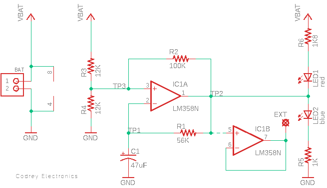
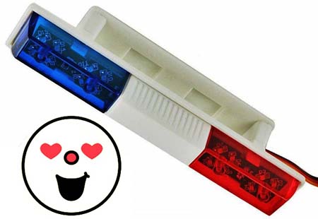
The micro-LED strobe I designed here is to drive a pair of LEDs – one red and one blue – which is proposed to be used in a radio-controlled (RC) toy car running on a 9V battery. The complete schematic of the micro-LED strobe is provided below.
The parts I used are listed here:
- LM358 IC x1
- Red LED 3mm x1
- Blue LED 3mm x1
- 12K ¼ w Resistor x2
- 100K ¼ w Resistor x1
- 56K ¼ w Resistor x1
- 8K ¼ w Resistor x1
- 1K ¼ w Resistor x1
- 47uF/25v Electrolytic Capacitor x1
- JST connector 2-Pin x 1
If you know what you are doing, then you can safely operate this circuit with DC voltages in the range of 5 to 12 volts. As you can see, I added a dual op-amp – the LM358 – to the circuit. What the first op-amp (IC1A) does is to generate a square wave with a fixed frequency and duty cycle for flip-flopping a pair of LEDs (LED 1 & LED 2) connected at its output. The second op-amp (IC1B) functions as a non-inverting buffer, so it provides the same square wave signal through its output (EXT). Needless to say, this buffered square wave signal can be used by external circuitry if necessary.
The LM358 IC consists of two independent, high gain, internally frequency compensated operational amplifiers which were designed specifically to operate from a single power supply over a wide range of voltages. As said before, IC1A circuit is an astable oscillator.
The frequency of oscillation is decided mainly by C1 and R1 but is also dependent on the threshold voltages (TP3) the combination of R2, R3, and R4 generate when IC1A output (TP2) is high or low. In my prototype, the oscillator frequency is roughly around 1.6 Hz.
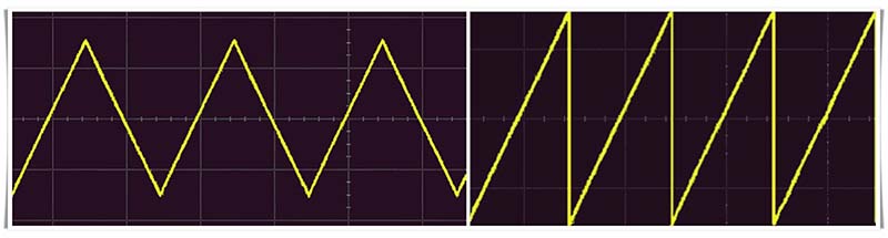
The output at the capacitor C1 is formed like a triangle wave (note – the symmetry of this triangle wave is influenced by the potential divider). If you need such a wave for another application, you can simply tap the requisite signal from Pin 2 of IC1A (TP1).
At this point, also note that in a triangular wave, the voltage varies linearly with time. The edges are called ramps because the waveform is either ramping up or ramping down to certain voltages. A sawtooth wave looks similar in that either the front or back edge has a linear voltage response with time, but the opposite edge has an almost immediate drop.
Now to the second op-amp (IC1B) inside the LM358 which is configured as a voltage buffer by connecting the input signal to the non-inverting (+) input, and connecting the output directly back to the inverting input (-).
See, an op-amp voltage buffer mirrors a voltage from a high-impedance input to a low-impedance output. In other words, a voltage buffer (also known as a voltage follower or a unity gain amplifier) is an amplifier with a gain of 1. A voltage gain of 1 means that if the input voltage goes up by, then the output voltage is also designed to go up by the same ΔV.
Even though a gain of 1 doesn’t give any voltage amplification, an op-amp buffer is pretty useful because it prevents one stage’s input impedance from loading the prior stage’s output impedance, which causes undesirable loss of signal transfer.
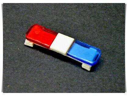
The red (LED1) and blue (LED2) are simple visual indicators with independent current limiting resistors (R6 and R5). These two LEDs flash like a strobe (on and off alternately) thus creates a noticeable visual effect.
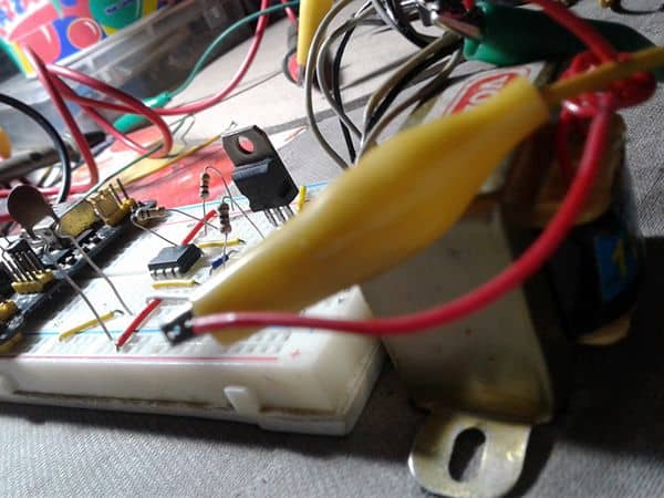
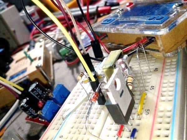
This is my quick breadboard test setup. Sorry for the pathetic snap!
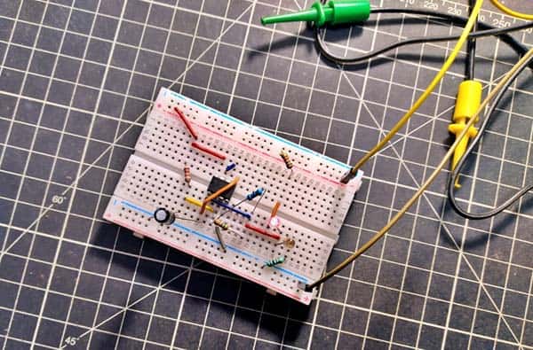
Frankly, I tried to make my model as small as I possibly could. I guess I could have used SMD parts, but I’d have to order some “free” PCBs from a Chinese fab house and need to pay “$$” for shipping! I’m not looking to spend much money on this because I can easily put this together with the thru-hole parts I already have.
Anyway, you are free to design a customized PCB and make the whole assembly as a minuscule module using SMD parts. Just how small is it? I bet you could fit this inside a small rectangular enclosure. So, you can 3D-print something to put it in. Additionally, you can make changes to this basic design to use more LEDs.
Finally, this circuit has plenty of fun and practical applications. I’ve seen many examples online that have been made by others and they’re basically a few red and blue LEDs in a box connected to a battery and a switch. I can do much better than that – I plan to modify this crude design idea using a few more components, leaving the updated design with enough room for more LEDs and a digital/remote on-off control mechanism. Nevertheless, it will definitely little enough that the whole thing will fit comfortably inside a compact enclosure.