Everybody knows that a dog barks to get his/her master’s attention, to alert other dogs, to announce that they’re scared or in danger, and for a variety of other reasons too. However, if your dog might constantly be making barks, certainly that’s not fun for you or your angry neighbours!
A neighbour came to me a few weeks ago asking for help gathering an electronic device to mute his over-stimulated puppy. Of course, he can use an electronic dog silencer or a dog whistle to warn his puppy that she needs to be quiet (such a common device lets out a high-frequency sound that only dogs can hear). But with numberless electronic dog silencers/whistles out there on the market, it can be very difficult to know which device is going to be right for my neighbour and his dog. So finally, I decided to build a new one using common components I had laying around!
I had looked at many commercial dog silencers and some hobby circuits on the web that produce an ultrasonic signal. Most of them use a little circuitry to drive a small ultrasonic transducer. And so, I developed a low-budget experimental device for him which’s nothing but a mere adaptation of the same old school way. Below you can see the project documentation, as usual, packed with all the key information you need about constructing your own dog silencer/whistle. Well, let’s get started!
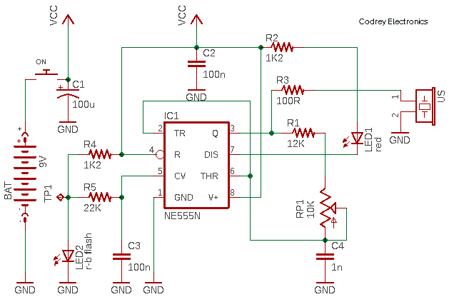
First off, see the schematic:
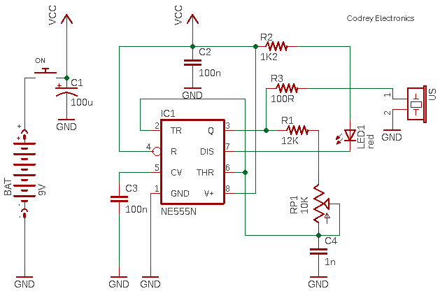
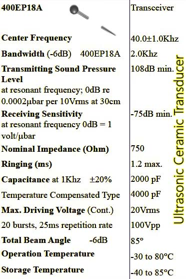
This circuit will run on a 6F22 9V battery. Here, the NE555 (IC1) is configured as a free-running high-frequency oscillator to emit 40kHz frequency to drive an ultrasonic transducer (US). The oscillator frequency is determined by the in-circuit values of the RC timing components R1-RP1-C4. This design was tested using the 400EP18A ultrasonic ceramic transducer (see its key specs below) because it’s a stock part. But you can try the more familiar T40-16B ultrasonic transducer without any circuit alteration. The red indicator (LED1) lets you ‘see’ the 40kHz tone!

Ultrasonic sound has been used for over a century to successfully train dogs, and now you too can stop barking from anywhere that you have a clear line of sight. Since some dogs take longer to train than others, you’ve to wait for a few weeks to get the result. A wide variety of components and design methods can be used for this project. The particular components used in this design was chosen based on availability and price. By no means is the solution presented the best or the only way to achieve the desired results, but it is definitely a viable solution.
Even though 9V battery operation is recommended, you may try a 12-15V dc power supply for running the device because with 9V the output will not be quite powerful. Also, bear in mind that the basic circuit demoed here sometimes needs to be modified according to the different characters of impedance, phase angle, and resonant frequency while driving a different type of ultrasonic transducers.
A bit of composite theory: Ultrasonic transducer characteristics vary with operating frequency and temperature in a complex manner that is different for each construction. In principle, for frequencies approximately 0.1 octave on either side of the resonant frequency the transducer looks like a capacitor. The current through the transducer will lead the voltage developed across it by 90°. As the resonant frequency is approached, the voltage across the transducer will decrease to a minimum at the resonant frequency (minimum series impedance) and the current will increase proportionally. The phase lead to this current relative to the voltage will decrease to zero near the resonant frequency and the transmitter will then appear to be a pure resistance. And, as the frequency is increased above the resonant point, the current may now lag the voltage by an increasing amount (Maximum of 90°) as the voltage across the transducer climbs to a peak which is defined as an “anti-resonant point”. During this transition, the transducer appears to have an inductive characteristic!
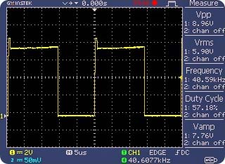
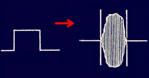
As you might be noticed, the ultrasonic transducer in my design is driven with a dc pulse waveform. Note that the application of a dc pulse of sufficient amplitude will cause the transducer to ring at the selected resonant frequency. The ultrasonic output will be a damped ringing waveform as shown below.
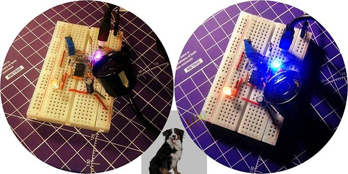
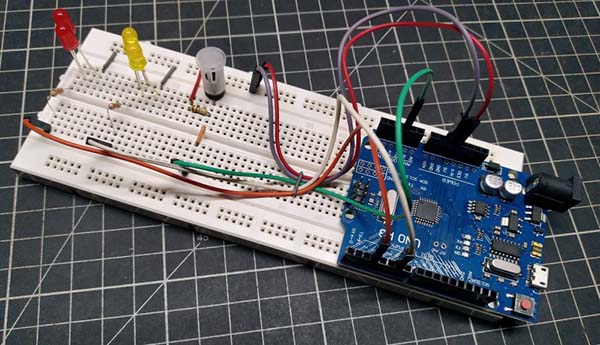
Coming back to my project, once I had what I thought was a running circuit, I needed to do a field test to see if dogs would really pay any attention to it. I made a quick (and stable) breadboard prototype I could carry around and tested it on a number of street dogs (some hear it, some hardly pay attention). Luckily my neighbour’s puppy seriously listened to it at times, thus I decided to move farther with my crude dog silencer/whistle idea. Finally, I crammed my stripboard assembly into an acrylic project box and fixed up the external push button switch, dc input jack, and the signal indicator LED.
To effectively use any electronic dog silencer/whistle device, you want to consider it as a dog training tool. That’s going to take some time on your side, but you’ve a chance of getting reasonable outcomes if you duly train your pet dog with great patience!
A trivial revision!
Although I got the dog silencer/whistle circuitry to behave as planned, I could not feel the ultrasonic vibrate! So, I slightly modified the basic schematic to use a bicolor flashing LED to swing the ultrasonic output freely but within a narrow range. The bicolor flashing LED (LED2) together with two resistors (R4-R5) wired to the control voltage input (Pin 5) of the timer chip (IC1) can be seen in the revised schematic below.
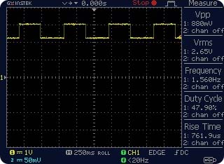
Here, the 5mm bicolor flashing LED (red and blue) is wired to generate a clean ‘clock signal’ with a frequency close to 1.6Hz (see the TP1 scope grab). This clock signal switches the 40kHz free running oscillator thru pin 5 of IC1. Be prepared to fiddle with the value of resistor R5.
Design Flaws?
There’re no serious flaws in this ‘domestic’ project as it’s the mere adaptation of a proven textbook design. However, I utterly failed to follow the common practice of driving my ultrasonic transducers through a voltage booster circuitry to make them happy with a 20vp-p (or so) drive voltage. Actually, I also messed around with some “booster coils” to generate the piezo driving signal with limited result. It’s not your dog’s fault if it barks and bites when you fire your dog silencer/whistle device up – perhaps it’s because of my design’s fault (ha ha)!

Offbeat: As a follow up to this original project, I successfully designed the core part of a microcontroller based ultrasonic generator. Now I’m waiting on a couple of “Ultrasonic IFT” (www.midassensors.com) samples from a seller abroad to play with. Full details of the new project can be found in an upcoming post. Thanks to everyone who reads and shares my post – you make all of this worthwhile!
Acknowledgment: Thanks to various online resources aided in this project!
hi TK… I have troubles with squirrels getting into my attic space as the cold weather here sets in. I think I may try something like this and see if they respond to it. I did hear that squirrels have been known to EMIT about a 50kHz call at times… so I’m hoping they can hear this at a slightly lower frequency. I’ll try and put an amplifier of sorts on it (or just an LC impedance matching circuit) to see if I can hit it with “more juice” 🙂 Thanks for the idea and motivation 🙂
Russ; Welcome, and thank you for your inspiring comment!
I hope the revised design concept works for your specific purpose. Good luck on your project.
BTW, here is a quick reference for you. Seems this helps you a little. https://www.linux.com/training-tutorials/how-build-arduino-pest-repeller-linux-part-1/