The capacitor is the basic electronic component that is used for storing, surge suppression and filtering. It is a widely used and important component in the family of electronics. Like resistor, capacitors are passive components to store an electric charge. The amount of charge that it can store depends on the distance between the plates.
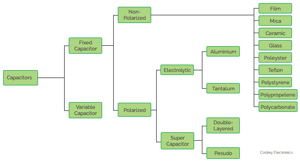
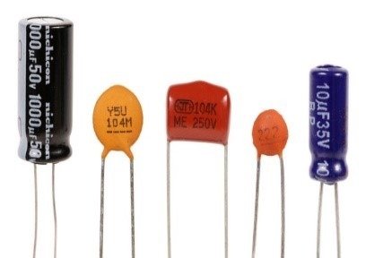
There are various kinds of capacitor available in different shapes and sizes depends on its dielectric material and voltage rating. It can be selected according to the application of the circuit. To know in detail, we will start with the structure of a physical capacitor.
Construction of Capacitor
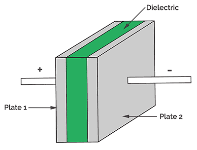
The device consists of two conducting metal plates which are separated by an insulator (a material which do not allow the passage of current) called dielectric. The conducting material is made up of aluminium or other metal and the dielectric can be made up of ceramic, glass, paper or plastic. The metal plates of a capacitor can be either square, circular or rectangular, or they can be of any other shape and size. A two lead is brought out from each plate to enable the device to be connected to a circuit.
When a voltage is applied to the two leads through a battery source, the charge deposits on the plates of the capacitor. As long as this voltage (potential difference) is equal to battery voltage (E) the circuit is in balance condition. When we break the connection of the battery the charges cannot flow away and the voltage remains stable between the two plates. This combination of two plates, which are separated by an insulator and which are able to store some amount of electricity is called a capacitor or condenser.
Dielectric behaviour of capacitor
The behaviour of capacitor changes with respect to the dielectric material and dielectric constant. Different dielectric materials differ in their ability to pass electrostatic force. Materials having high dielectric constant are better when compared with lower dielectric materials since they act as insulators.
The permittivity is the measure of the dielectric. It is equal to the product of the permittivity of free space (ϵ0) and the relative permittivity (ϵr) of the material being used as the dielectric.
ϵ = ϵ0 x ϵr
Dielectric constants for some of the dielectric materials are given as:
| Material | Constant |
|---|---|
| Vacuum | 1.0000 |
| Air | 1.0006 |
| Paraffin paper | 3.5 |
| Glass | 5 to 10 |
| Mica | 3 to 6 |
How does a Capacitor work?
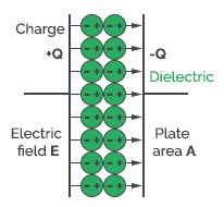
When a voltage source is applied, electrons from the plate connected to the +Ve side of the battery will flow to the negative side of the battery and are pushed towards the other side of the capacitor plate. Electrons can’t be able to pass through the capacitor because of the insulating material i.e. dielectric. So, the electrons will start accumulating on the other side of the plate. Now the top plate will get positively charged and the bottom plate will be negatively charged. At this point, the capacitor is fully charged creating an electric field (E) between them and current is not able to pass through the circuit because of the dielectric material.
In a DC circuit, a capacitor can charge up to its supply voltage i.e. the voltage applied is equal to the voltage across the capacitor. Since DC can flow only in one direction because of the dielectric it blocks the current flow when it is charged.
The capacitor allows alternating current to pass. The reason is, in AC circuits the alternating current charges the capacitor in positive half cycle and discharges during the negative half cycle. Hence, the output current changes in phase with the AC voltage.
Charging of capacitor
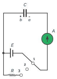
The charging and discharging cycle of the capacitor can be demonstrated using the following figure.
Whereas ‘E’ is the battery voltage, ‘A’ is the ammeter, ‘C’ is the capacitor and ‘R’ is the resistance. If the switch is turned to position 3, the electrons on the plate ‘a‘ now will flow through the resistance ‘R‘ in order to supplement the electrons shortage on the plate ‘b’. We thus obtain a movement of electrons from the plate a to b and the Ammeter (A) will now deflect in the opposite direction.
The electron current will continue flowing until there is no longer potential difference between the two plates. We say then that capacitor is discharged. In position 1 of the switch, the capacitor was charged.
Discharging of capacitor
In open circuit, the capacitor works as direct current. Now the capacitor starts discharging
through the load. The potential difference between the plates gradually decreases down to zero. This is the falling state.
Let’s say, for example, if you have a battery (E) connected to a capacitor circuit, the battery will charge the capacitor completely.
Even if you remove the battery, the capacitor can hold some amount of electric charge and power until it gets discharged. In this case, capacitor works like a rechargeable battery.
Voltage Rating
Every capacitor has a maximum voltage rating. This plays a mighty role in determining the circuit performance. In the initial state (open switch), when there is no power the capacitor is uncharged. When some amount of power is driven through a capacitor (closed switch) the capacitor starts charging. Now, the capacitor is partially charged.
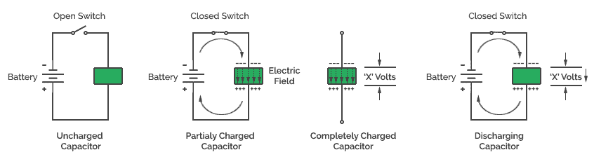
When the capacitor reaches a maximum voltage rating it is a completely charged capacitor and whenever a load is connected it starts discharging. The voltage rating of the capacitor is specified by the manufacturer and it should be selected based on the application requirement.
Capacity
The electricity is represented in terms of electric charge ‘Q’ and is directly proportional to potential difference V. The total amount of charge can be stored in a capacitor is given by the equation, Q = CV i.e. multiplying the capacitance value and the voltage applied to it gives the total charge.
Q = Total electric charge in Coulombs (either positive or negative)
C = Capacitance in Farads (F)
V = Potential difference in Volts (V)
Capacitance of Capacitor
The capability of a capacitor to store electricity is called capacitance and is expressed in Farads. The capacitance is directly proportional to the dielectric permittivity & surface area of the plates and inversely proportional to the gap between the plates.
![]()
C=capacitance determines how much of a charge difference the capacitor holds when a certain voltage is applied (F),
ε= absolute permittivity of the dielectric (F/m),
A=surface area (m2),
d=distance between the plates (m)
Factors that affect capacitance
Okay. How do we increase the capacitance?
- Smaller the distance between the plates more the capacitance. Because capacitors store charge in the form of an electrical field. Closer space yields more force results in a greater field. The electrical field is stronger when the plates are closer together. That’s why the capacitance increases when the distance between the plates decreases.
- The large plate area gives more capacity to store charge.
- Capacitance also depends on the dielectric material. Introducing a dielectric in a capacitor decreases electrical field which decreases the voltage which increases the capacitance. A dielectric with a high dielectric constant is a better insulator than a dielectric with a low dielectric constant.
Capacitor characteristics
Here are some of the properties of the practical capacitor.
- Nominal Capacitance
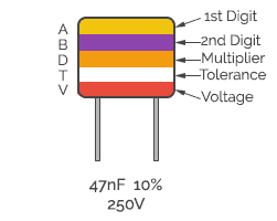
The capacitance of a capacitor is written as numbers or letters or it may have a colour code on the body of the capacitor based on the type of capacitor. The capacitance can range from 1pico factor to 1 farad. The tolerance of a capacitor varies from -20% to 80%.
The capacitance may change with the working temperature and the circuit frequency.
- Working Voltage
The working voltage is most important of all the characteristics. There is a working voltage is written on the capacitors which refer to the maximum voltage that can be applied across the capacitor. It refers the DC voltage.
It is safe to operate the capacitor within its rated voltage. Otherwise, it may damage the capacitor. If the voltage applied is greater than the working voltage of the capacitor, the dielectric will breakdown. The working voltage depends on the dielectric material and the thickness of the dielectric. The working voltage depends on the dielectric material and the thickness of the dielectric. So always the working voltage of the capacitor is the maximum voltage of the capacitor that can be applied. In practice, a capacitor should be selected so that its working voltage is at least 50% greater than the highest effective voltage applied to it.
Sometimes in capacitors AC voltage is also written on the capacitor. It refers to the RMS value and not the working voltage. The actual working voltage for the AC must be 1.414 times (i.e. Vm=Vrms x √2) greater than the RMS value quoted on the capacitor. Also, the specified DC voltage is valid only within a certain temperature range, -30°C to +70°C. Common working DC voltages are 10V, 16V, 25V, 35V, 50V, 63V, 100V, 160V, 250V, 400V and 1000V.
- Tolerance
Tolerance is how much more or less you can expect capacitors actual capacitance to be from its rated capacitance which is printed on the capacitor. Tolerance rating is expressed as plus (+) or minus (-) value in ± Pico farads for low-value capacitors which are less than 100pf or as a percentage (± %) higher than 100pf for high-value capacitors. It can range from -20% to +80% i.e. If a 100µF capacitor with a tolerance of ±20% can vary from 80µF to 120µF.
- Leakage current
Leakage current can be defined as that it is unwanted energy which flows in the device. It is a result of the fact that metal plates in the capacitors are not perfect. It indicates the amount of current flows through the capacitor. The leakage current is very low in film type capacitors and it is very high in electrolytic capacitors.
- Working Temperature
Capacitance may vary with change in temperature because of the dielectric properties. The normal working temperature of capacitors vary from -30ºC to +125ºC. These changes in the temperature sometimes cause damage to the circuit.
- Polarization
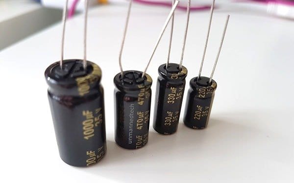
Majority of the electrolytic capacitors are polarized. So, we need to connect the capacitors correctly when it is connected to the power supply.
If the polarity of the capacitor is incorrectly connected, the oxide layer inside the capacitor may break which can cause high current to flow through the device results in damage to the circuit.
- Temperature coefficient
There will be a maximum change in capacitance within in a certain range of temperature. This is indicated by temperature coefficient. It is expressed as parts per million per degree centigrade (PPM/oC) or as a percentage change with a particular range of temperatures.
Class 1 capacitors (like mica) are highly stable with temperature which has zero temperature coefficient. The Class 1 capacitor is stable when compared to Class 2 capacitors type. Their capacitance will increase by increasing the temperature.so this gives a positive temperature coefficient.
Capacitor Unit
The unit of capacitance is measured in terms of a farad, mostly in microfarads. Capacitance determines how much amount of charge it can store. Higher the capacitance, more capacity to store charge. A one-farad capacitor stores one coulomb (unit of charge Q) which is equal to 6.28 × 10¹⁸ of charge when a potential of 1 volt is applied across the capacitor.
| Farad | Factor | Equivalent weight |
|---|---|---|
| Farad (F) | 1 | 1F |
| Kilo farad (kF) | 103 | 1000F |
| Milliard (mF) | 10-3 | 0.001F |
| Microfarad (µF) | 10-6 | 0.000001F |
| Nano farad (nF) | 10-9 | 0.000000001F |
| Pico farad (pF) | 10-12 | 0.000000000001F |
If the capacitance value ranges from farad to kilo farad, these capacitors are called as super or ultra-capacitors.
Capacitor symbol
Capacitors symbol can be identified as polarized, non-polarized and variable. The schematic of the symbol is represented by the following symbols:
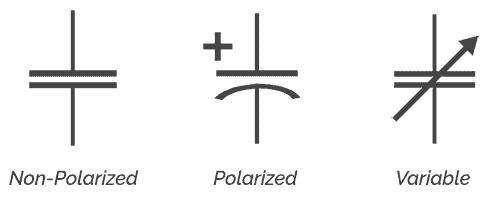
A non-polarized capacitor has no polarity. It can be connected in either side of the capacitor. A polarized capacitor which has a polarity that means can be connected in only one way. These types of capacitors have two leads: Anode (Negative) and Cathode (Positive). The variable capacitor is a type of capacitor whose capacitance can be changed mechanically or electronically.
Applications
We know that a capacitor is used to store energy. Different types of capacitors have different applications. Some of the applications include
- It can be used in amplifiers to block DC and allow AC to pass,
- The coupling capacitor is used to couple or links together only the AC signal from one circuit element to another.
- Decoupling capacitors can suppress voltage fluctuations and noise in power supply circuits
- In filtering circuits to block lower frequencies and pass higher frequency,
- Tuning radio circuits, transmitters, to smooth the output signal of power supplies,
- Used to store charge in applications like a flash on a camera.
Conclusion
Other than above, Capacitors offer power factor correction, back up of data in Real-time Clocks (RTC), and Battery powered applications using supercapacitor. Typically capacitor has a capacitance of 1 Farad when a charge of 1 Coulomb produces one volt across it. For practical purposes, this farad is subdivided into smaller units such as microfarads, Pico farads and Nanofarads. Another interesting property of the capacitor is electrostatic shielding, which means when a third plate connected to earth is inserted between the two plates, the capacitance between the two plates will be reduced to zero.