This is a simple design guide for making your own really nice lighting for your home, office, shop, lab, etc. by using the common and inexpensive LED strips available in various colors. The intent is to provide an efficient driver circuit for the light strips thus you can drive your LED strips by a microcontroller to create wonderful lighting effects as desired.
LED Strip
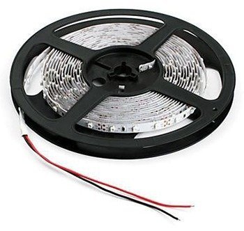
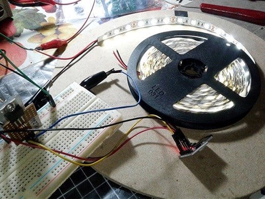
I’ve both warm white and cool white LED strips (non-waterproof) bought from Amazon so that I can tweak the warmness of the light depending on my moods. Shown below is the photo of my 5-meter warm white flexible LED strip built with 300 LEDs (SMD3528 type). The 12V LED strip has 60 LEDs per meter and requires about 4.8W for 1 meter, thus a total of 24W @ 12V is necessary to drive the whole strip. Note that current consumption of a single chip SMD3528 LED is 80mW.
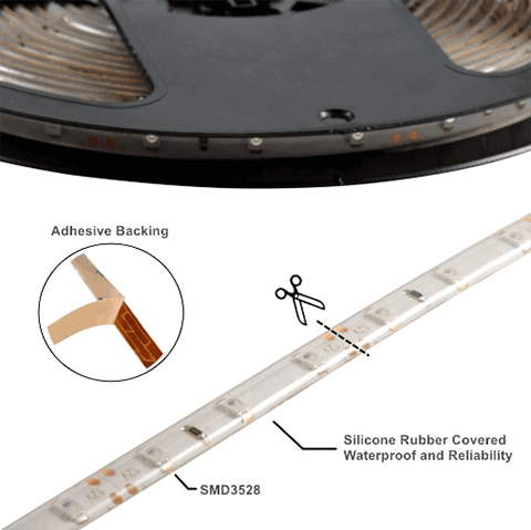
And, here’s its waterproof version the same flexible LED strip good for both indoor & outdoor lighting applications.
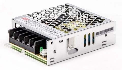
Since the LED strip calls for a 24W@12V power supply, it’d be better to use one 12V/36W smps adapter as it can cater decent current beyond the minimum necessary. Shown below is the photo of my 12V/36W industrial smps adapter.
LED Driver
Driving a 12V LED strip with an N-channel power mosfet is pretty simple, but we should consider some design facts. Because here we are driving the power mosfet with TTL level signals from a microcontroller i.e. typically with 5V (or 3.3V) , and at current levels less than 40mA. Popular power mosfets broadly tried by hobbyists for similar applications are IRF540 and IRFZ44. However I’d like to use a logic level mosfet IRLZ44N rather than the handed-down type. Wherefore? Let me explain!
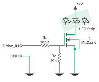
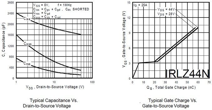
Simply, a logic level MOSFET is designed to turn on fully from the logic level (5V/3.3V) output of a microprocessor whereas the standard MOSFET runs from around 10V. Since the MOSFET is commonly treated as a voltage controlled device, a gate current-limiter resistor is not very necessary in the simplistic model of the application. However, you can see a resistor (R1) in my LED Driver circuit because I worried* much about the ‘gate capacitance’ (and switching time) of the MOSFET. One datasheet of IRLZ44N shows 1700pF typical input capacitance and 48nC total gate charge, it quotes a 95nS rise time with a 3.4Ω gate resistor as well (refer next graphs).
Based on my maths and observations, a 100Ω resistor looks like a good tradeoff right here (able to apply a voltage sufficiently higher than Vth to the gate, and sufficiently charge the input capacitance). An appropriate resistor value must be selected always because it impacts the switching speed and therefore the switching loss of the MOSFET. The second resistor (R2) is added deliberately to reduce the gate-source voltage to 0V when the input signal is open-circuited. Admittedly, we often wants to drive LED strips with PWM signals rather than mere on/off signals. That’s why a 100Ω resistor (lower value than my calculated 220Ω) is used as R1. Empirically, I found that the 100Ω value not only maintains a good switching speed but also ensures enough protection for the microcontroller I/O port (see succeeding note).
In a nutshell, for most Arduino projects just a 10K resistor from gate terminal of the MOSFET to its source terminal and directly connect the gate to one I/O pin of Arduino will do it just fine. However, the gate will act like a capacitor and hence sink or source quite a bit of current when the I/O pin state changes. Since the Arduino I/O pins are not supposed to deliver/tolerate more than 20 mA (40mA max), without a gate resistor, there’s nothing to restrain the current, which isn’t good especially when using PWM (in the long run this might kill the microcontroller).
*For a back-of-the-envelope calculation, in the datasheet of another common logic level MOSFET IRL530N, you can see that its “Ciss” is 800pF, “Qg” is 34nC, and “td(on) tr” is 60nS. If so it might take an average of 34nC/60nS = 560mA average current to charge the gate capacitance – far higher than that an Arduino I/O can support (wrong maths? Let me know), then a gate resistor is proposed to protect the microcontroller’s I/O pin!
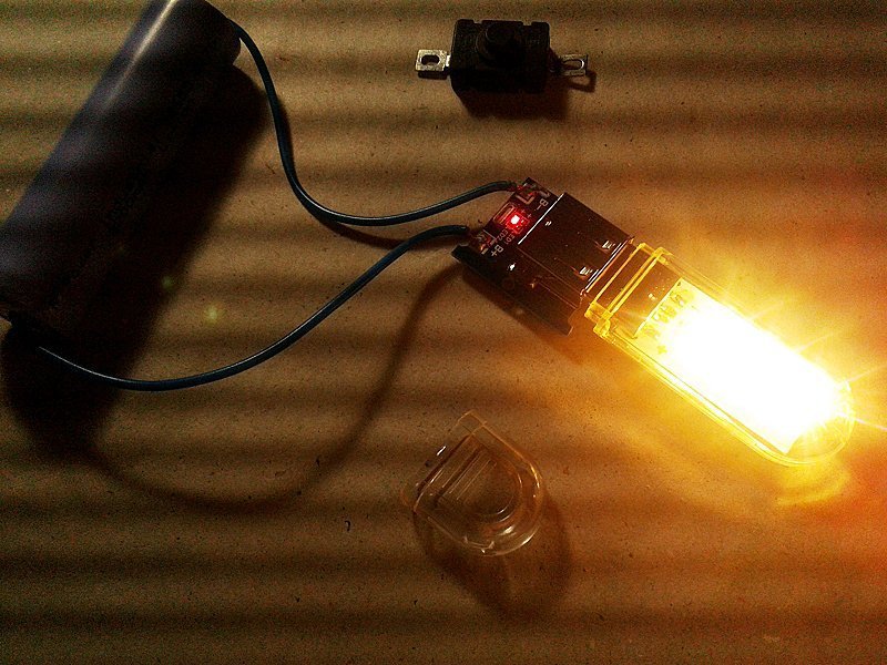
Real World Test
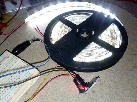
For an initial test of your LED strip driver setup, just pick up a Digispark (or Arduino Uno) board and upload the given “Fade LED” rude example code through Arduino IDE. For Digispark, connect its PB1 to the input of the LED strip driver, and for Arduino use D9. VIN header of both boards can accept 12V dc input, so route it straight but with caution.
/*
 * LED Strip Test/Example Code
 * For Digispark & Arduino Uno/Nano Boards
 * Refer LED Driver Schematic included in the article
 * Prepared by: T.K.Hareendran/2019
 * Published by: Codrey Electronics
 * Publisher URL: https://www.Codrey.com
 */

void setup()
{
  pinMode( 1, OUTPUT); // Digispark PB1 as LED Drive O/P
  // For Arduino, Comment the line above & Uncomment the line below
  // pinMode(9, OUTPUT); // Arduino D9 as LED Drive O/P
}

byte b = 0;

void loop()
{
  analogWrite(1, b); // For Digispark
  //analogWrite(9, b); // For Arduino
  delay(30);
  ++b;
}
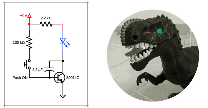
At last, one inexpensive 12V LED Strip Controller circuit for novices. Just connect your dc power supply and 5-meter LED strip to this non-microcontroller circuit, and rotate the potentiometer to adjust LED luminance from 1% to 99%. The circuit is nothing but a 555 IC based PWM controller with overall PWM frequency of 1.5KHz (determined by R3 and C3).
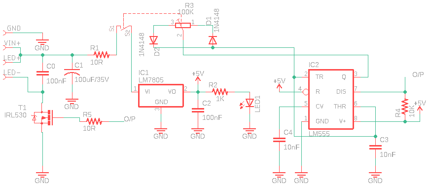
The 100n shunt capacitor (C0) is not very crucial but added intentionally to suppress possible ringing observed with lengthy LED strips!
Your 10K resistor should be on the other side of the 100 ohm in the first schematic. You’ve created a voltage divider, thus losing a percentage of the voltage to the gate. It would get worse with higher values of series resistor or lower values of pull-down resistor. I realize you’re only losing 1% here, but there’s no need to waste any of that MOSFET drive voltage. Every little bit helps when trying to achieve low Rds(on).
Stan: The 10K resistor is in the right place! You may refer page 8 of the PDF, available through this link for download https://toshiba.semicon-storage.com/info/docget.jsp?did=59460
It’s better to know how to learn than to know!