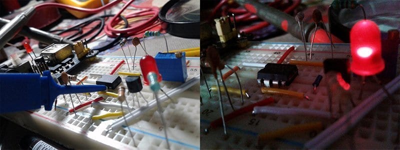
Once again, here is the circuit diagram of a little night lamp wired around the evergreen 555 tiny timer chip. The circuit, designed to run on a standard 6F22 9V battery, can be used as a fancy night light in your kids’ sleeping room. A built-in photo sensor in the circuit turns its ‘sleeping lamp’ automatically when their is very low (or zero) light level inside the room.
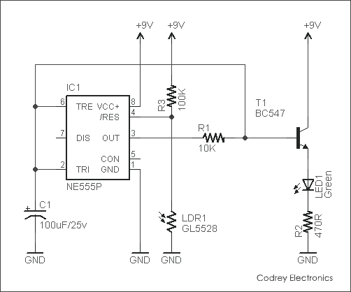
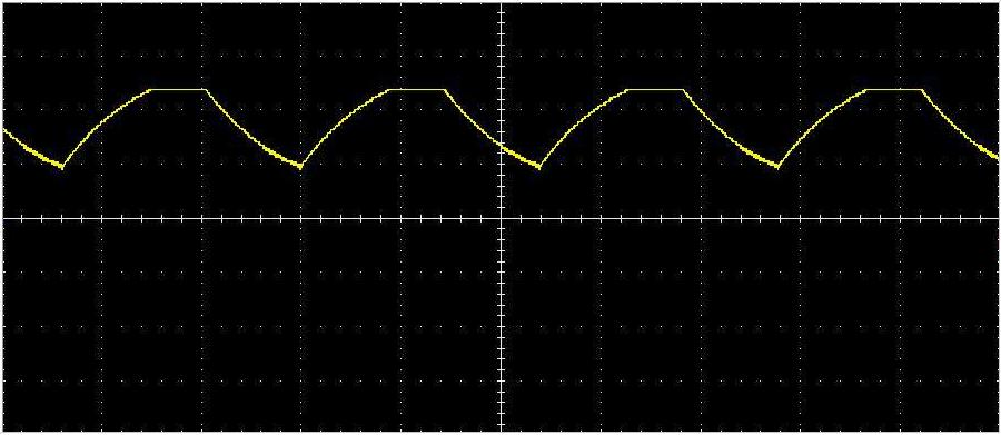
As can seen from the above circuit diagram, the NE555P (IC1) is wired as a square wave oscillator. The astable frequency is determined by the RC components R1 and C1. The voltage at the common junction of these two components changes between 2/3rd and 1/3rd of the supply voltage (here 6V and 3V). This voltage (varies in a near- triangular waveform) is connected to the base of the LED driver transistor BC547(T1). The transistor is wired as an emitter follower so the voltage at the emitter would be 0.6V lower than its base voltage (here 5.4V and 2.4V). Resistor R2 is the current-limiter resistor for LED1.
The photo sensor (LDR1) is connected to pin 4 of IC1. Pin 4 is the ‘Reset’ terminal of the chip pulled–up by an internal 100K resistor. Here, the LDR and the external 100K resistor (R3) forms a potential divider that sets the voltage on pin 4 below 0.8V when there’s enough light level, and above 0.8V in case of total darkness. This setup provides automatic switching of the night light!
Next is an image that may make you curious. It’s nothing but a random capture from my oscilloscope probed at the base of the BC547 transistor. Since the given circuit is a basic one, you can start your own next-level experiments to shapeup the wave form (also take a look at the dc offset).
Further, if you want to disable the automatic switching function, just unplug the photoresistor from your circuit. That’s all!