Perhaps, the most ideal rechargeable battery chemistry for industrial electronics today is the LiFePO4 (lithium iron phosphate) battery. This newer type of lithium solution is inherently non-combustible and best known for its strong safety profile because of the extremely stable battery chemistry. Besides, LiFeO4 offers excellent thermal constancy which provides an increase in safety over lithium-ion batteries.
Like Li-Ion (Lithium-Ion) batteries, LiFePO4 batteries also call for a dedicated charger to ensure better safety and prolonged lifetime. In this article, you can see a comfortable solution to make your own single-cell LIFePO4 charger with the help of an inexpensive battery charger module TP5000.
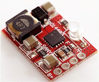
TP5000 is a compact charger module (available online), based on the TP5000 charge controller chip designed to charge either one Li-Ion or LiFePO4 battery. The module accepts input voltage in 4.5V–9V range and its “configurable” full charge/termination voltage is 4.2V or 3.6V. The battery charging current rate can also be modified simply by changing the value of a single onboard chip resistor. I got my red-module from an Amazon dealer, without the bicolor indicator LED soldered in!
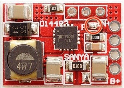
The module has 4 connection pads IN+/GND/GND/B+, where IN+ is the dc supply input and B+ is the battery output (with middle ground connections common to both input and output). By default the module is configured as a Li-Ion charger so you should remove the solder jumper “F” (next image) to use it as a LiFeO4 charger. The 0Ω jumper (000) sets the pre-charge/trickle current to 10% of the battery current, and the 0.1Ω resistor (R100) limits the charging current to 1000mA (1A). Adding one more 0.1Ω resistor in parallel with the existing R100 will raise the charging current to 2000mA (2A) but then a heatsink must be added to the controller chip. Likewise, replacing the 0Ω jumper with a 50KΩ resistor will raise the pre-charge current to 20%.
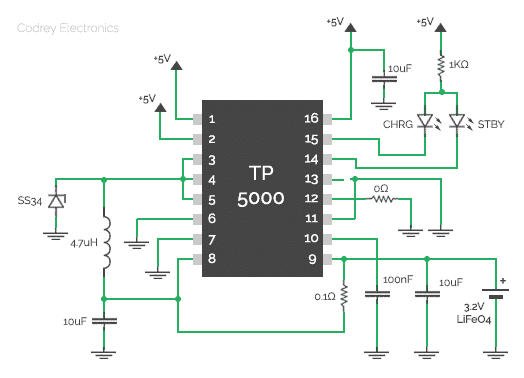
The 5mm (common-anode) bicolor LED supplied with TP5000 module fits directly into the vacant trio solder pads atop. Here, one color is for standby (right) and the other (left) is for charge indication. Refer the following schematic traced by me.
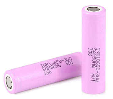
The module was tested with a 5V/1A USB power supply plus one 3.2V/1500mAh LiFeO4 battery (18650 type). Everything on the module stays fairly cool, and the charging process is flawless (after charge termination, it restarts when battery voltage drops to about 3.4 volt). Certainly it’s not only a right module for charging 3.2V LiFeO4 batteries from USBs, but also the wide input voltage range makes it compatible with cheap solar panels. Give it a good try!
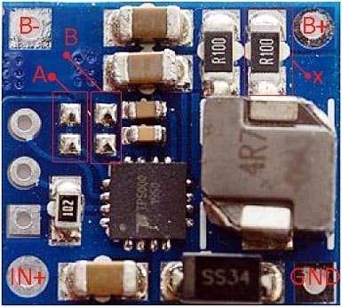
This is another charger module – the blue version – based on the same TP5000 charge controller chip. This module is configured as 2000mA (2A) charger by default, but do make and/or break two onboard solder-jumpers if demanded by your specific application. Jumper A is for battery selection (open=LiFeO4) and jumper B is for pre-charge/trickle current management (closed = 10%). Further, it’d be better to bump off one R100 resistor (X) from the module if the battery is a 18650 type LiFeO4.
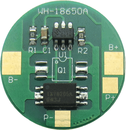
You can buy LiFeO4 batteries with built-in Protection Circuit Module (PCM) which defends the battery from short circuit, overcharge, deep discharge, etc. If your battery is not a type equipped with the electronic protection circuit, still it’s possible to add a bit of safety by tying it with a readymade protection circuit board (see below).