Sometimes you may need to make a battery-operated lamp flasher suitable for a variety of applications. In this post you will see the design concept of a 555 timer based multipurpose LED flasher that requires only a minimal current to operate. First of all, you have to note that this power-thrifty flasher design is different from the traditional textbook circuits of 555 IC based LED flashers.
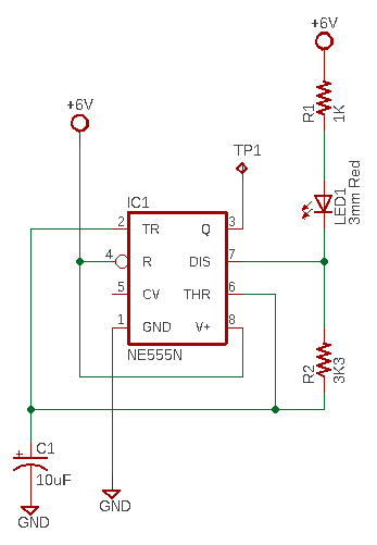
Well, let me get into my idea with its schematic. Here it is:
For its construction, you will need to gather the following parts:
- NE555N IC x1
- 3mm Red LED x1
- 10uF/16V Electrolytic Capacitor x1
- 1KΩ ¼ W Resistor x1
- 3.3KΩ ¼ W Resistor x1
- 6V Battery (1.5V x4)
Pretty simple approach, right? No costly microcontrollers or hard-to-learn codes. Even a novice can assemble it easily.
See, the 555 timer is configured as an astable multivibrator (AMV) in this project that does not require an external trigger input to create a cycling function.
AMV is the most common scheme that you will find the 555 timer used in. Here, capacitor C1 charges through components R1-LED1-R2. While the C1 is charging, the output at pin 3 is high. When the voltage across C1 reaches 2/3 of the supply voltage C1 discharges through resistor R2 and the output goes low. When the voltage across C1 drops below 1/3 of the supply voltage C1 resumes charging, the output goes high again and the cycle repeats.
Let us flip the theory book for a while. In this design, the LED is not wired to the output pin 3, but to the discharge pin 7 (which seems strange to many).
The discharge pin of 555 is connected directly to the collector of an internal NPN transistor which is used to discharge the timing capacitor to ground when the output switches low. Actually, the discharge pin is an open-collector terminal and has the same logic state as the output pin (if there is a pull-up resistor) as its transistor is switched by the same flip-flop that controls the output pin (but it can only sink current). No matter, nothing to fear in using it as such, as exploited in our current scheme!
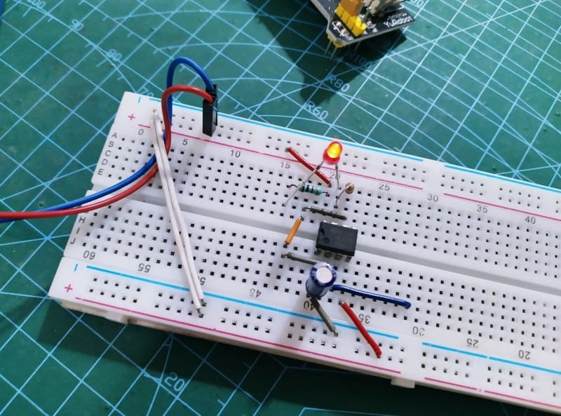
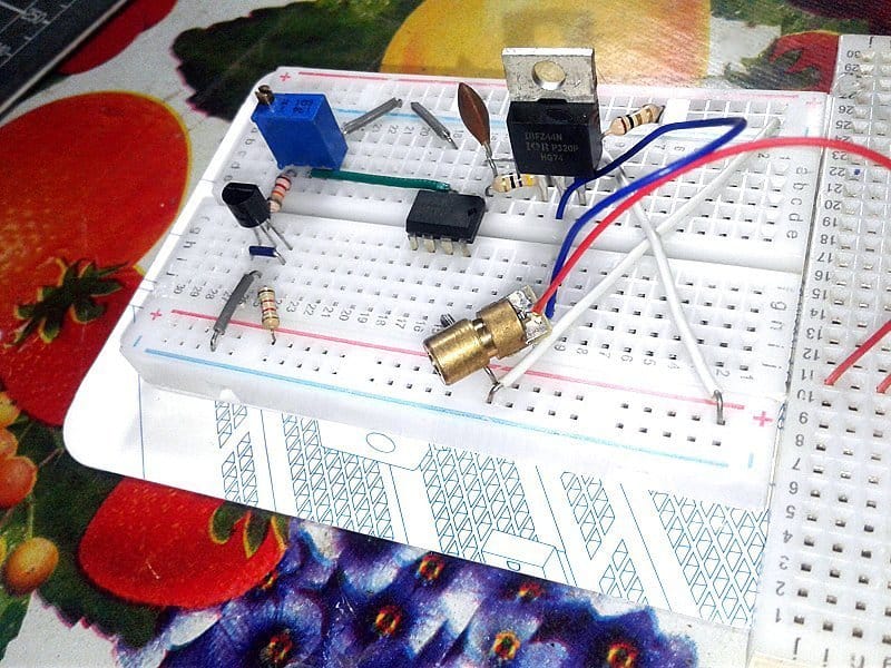
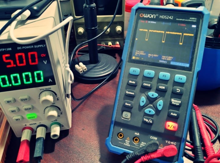
The circuit was first built on a breadboard and tweaked until the outcome was winning over. The setup was first tested using a regulated 6V (and 5V) DC power supply. Next, another extensive trial was performed using four 1.5V AA batteries connected in series (6V). Everything turned out successfully!
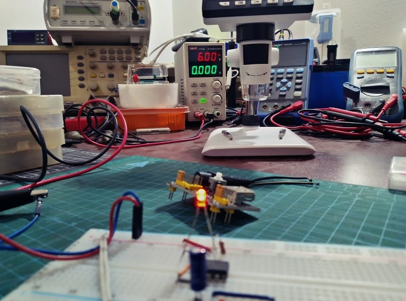
As my scope meter (and frequency counter) pointed out, the “free” output at pin 3 of 555 has a frequency around 0.8Hz, which has circa 80% duty cycle. As I have observed, the minimum operating voltage required for the setup to work smoothly is 5VDC.
Now it is your turn! With the relatively moderate current draw, the battery pack should last for weeks. So, you can try this nifty idea to make your own electronic keyhole finders, event notifiers, obstacle indicators, scarecrows, etc. Nothing going to stop you except your imagination!