Ever wondered how to build a multimode task light, and how to use a single button switch to change the mode of brightness? I too was curious about it so I studied many things about it through a lengthy Googling and built a tiny LED task light in the recent past.
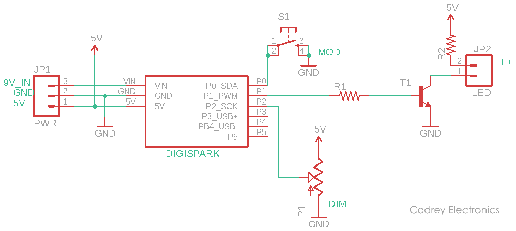
The tiny task light has a simple electronics core as you can see in the schematic shown below. Note that many of the backing constituents like the optics, enclosure, etc are true mechanical and are not looked at in this post. What’s really highlighted here are only the key parts that really define the behavior of the task light.
At the heart of the task light electronics is a Digispark Attiny85 microcontroller that gives the task light its user interface, including the number of modes and how those work relative to button presses. Needless to state, Digispark is an open-source hardware with lots of reference materials available online. You can also find numerous Digispark projects here in this website.
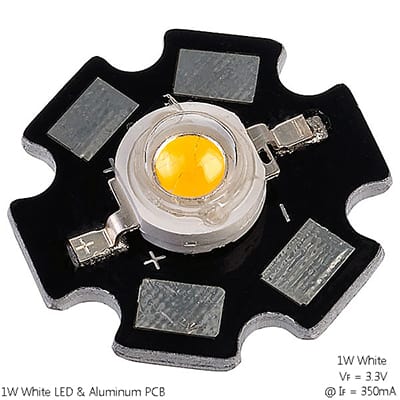
As clearly pointed in the above circuit diagram, the mode button (S1) is wired to P0 of Digispark while a potentiometer (P1) is wired to its P2. Digispark’s P1 works as the output pin here to drive the light source (LED) through a medium-power driver transistor (T1). The first resistor (R1) is the base resistor of the driver transistor, and the next one (R2) is the series-dropper for the LED. A standard 1W star white LED (1W white LED bead + Aluminum PCB) is suggested here as the light source of the task light.
The Digispark is probably the most basic and compact Arduino-like board I’ve worked with. It’s about the size of an USB A plug, powered by an Attiny85, and offers 1-5 I/Os depending on usage (2-3 typical). The VIN pin of Digispark takes unregulated 7-12V (9V typical), and the 5V pin takes regulated 4.5-5.5V. While powering through VIN pin, we can take regulated 5V from the 5V pin (thanks to the onboard voltage regulator). USB connector also takes 5V (4.5-6Vmay work but not advocated).
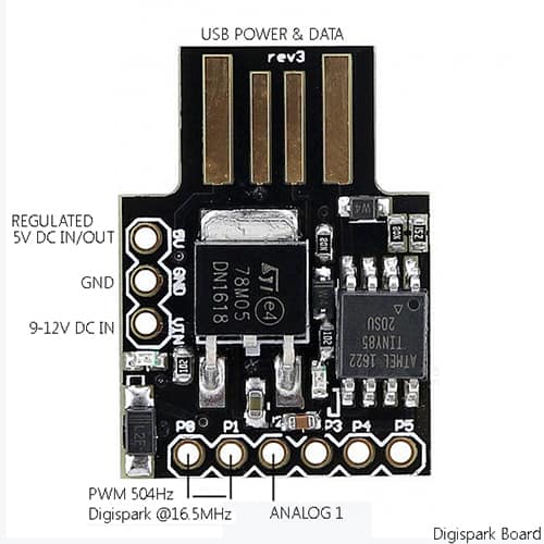
The Digispark has 4 built-in hardware PWM. Currently, only 3 of them are usable in the Arduino environment – P0-P1-P4. In the default implementation of PWM in Arduino IDE, hardware PWM frequency is 504Hz (P0 & P1) and 1007Hz (P4).
I will now summarize:
- P0 = AREF, I2C SDA, DI, PWM
- P1 = D0 , PWM, LED (Rev2)
- P2 = D/A, I2C SCK, ADC1
- P3 = D/A USB+, ADC3
- P4 = PWM, D/A, USB-, ADC2
- P5 = D/A, ADC0
- P0 is safe to use for digital I/O (5V)
- P1 is connected to the onboard LED (5V)
- P2 is safe to use for digital I/O or Analog input ADC1 (5V)
- P3 & P4 are used for software USB. Can’t use them and USB simultaneously. There’re 3.6V zener diodes connected with these pins, and P3 has a 1.5KΩ pull-up resistor as well
- P5 is 3V maximum I/O (limited current)
These are the key parts of the tiny task light:
- U1: Digispark Attiny85 (original or clone)
- T1: S8050 NPN transistor
- R1: 470Ω ¼ w (see note)
- R2: 4.7Ω 1W (see note)
- P1: 10K potentiometer
- S1: Momentary (N/O) tactile button switch
- LED: 1W star white LED
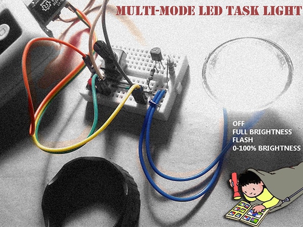
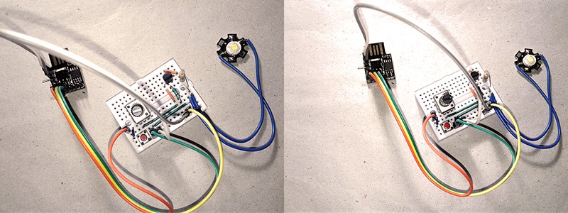
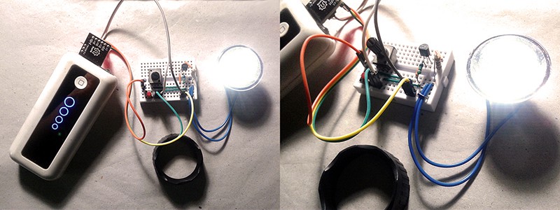
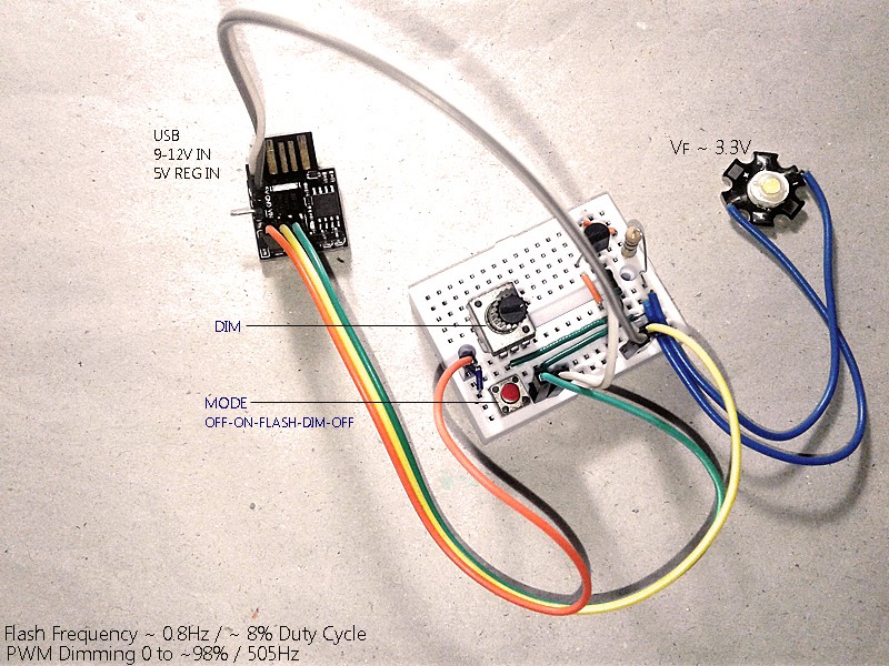
Admittedly, I was rushing to get a quick-and-dirty prototype together, and while the breadboard assembly looks ugly, it works great with a regulated 5VDC power supply source, and a cheap USB power bank.
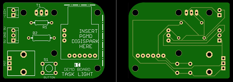
One of my not-too-distant goals is to rebuild this circuit on a devoted PCB, so it will sit rigidly on the enclosure rather than being tethered by a bundle of wires. See the proposed demo PCB artwork provided below (not to scale).
And, the code for Digispark:
/*
 * A Tiny Task Light
 * An LED Task Light with Digispark Attiny85,
 * And a High-Power White LED
 * Author - T.K.Hareendran / 07-2020
 * Publisher - codrey.com
 */

int lamp = 1; // P1
int button = 0; // P0
int knob = 1; // P2

int potval = 0; // Light Regulation
int mode = 0; // Mode selection

void setup() {

pinMode(lamp, OUTPUT);

pinMode(button,INPUT);
digitalWrite(button,HIGH);
analogWrite(lamp,0);

}

void loop() {

int val;
val = digitalRead(button);

if(val==LOW){
mode = mode + 1;

analogWrite(lamp,0);

delay(500);

for(int i = 0; i<5; i++){ // Mode Transition Signaling!
analogWrite(lamp,125);
delay(10);
analogWrite(lamp,0);
delay(30);
}

delay(500);

if (mode == 4){
mode = 0;
}
}

while (val == LOW){
delay(100);
val = digitalRead(button);
}

potval = analogRead(knob);

// OFF
if(mode==0){
analogWrite(lamp,0);

}

// ON
if(mode==1){
analogWrite(lamp,255);

}

// FLASH
if(mode==2){
analogWrite(lamp,255);
delay(100);
analogWrite(lamp,0);
delay(1200);
}

// DIM
if(mode==3){
analogWrite(lamp,0 + potval/4);

}

}
Back to the hardware, let me drop a line about the base resistor of the driver transistor. In principle, when a BJT works as a switch, it operates in a saturated state, which is when the resistance across the emitter-collector junctions is almost zero or negligible. Biasing the BJT with the right base resistance assures that it operates within the saturation region. It is needed to be fully conducting thereby exhibiting a minimum voltage drop – Vce(sat) – across collector-emitter.
The value of the base resistor can be calculated using the formula Rb = (Vi – Vbe)/Ib. To calculate the value of the base resistor, first find some key parameters (Vbe, hFE, etc) from the datasheet of the transistor proposed to be used in your circuit (Ib = Ic/hFE, and Vi is the base drive voltage available on that point). Further, when choosing a BJT to use as a switch you need to consider its maximum collector current Ic(max) and its minimum current gain hFE(min). Transistor voltage ratings may be brushed off for supply voltages less than 15V. Further reading http://www.bitsavers.org/pdf/ti/_Texas_Instruments_Electronics_Series/Walston_Transistor_Circuit_Design_1963.pdf
Likewise, an LED must have a resistor in series with it to limit the current to safe level. The value of the resistor can be calculated using Rs = (Vs – Vf) If. Vf and If can be found from the LED’s datasheet (Vs is the supply voltage). Note that the power rating of the resistor must be twice than the power dissipation calculated using P= I2 x R. You can use this pretty simple tool https://www.digikey.com/en/resources/conversion-calculators/conversion-calculator-led-series-resistor as it’s an easy to use LED Series Resistor Calculator.
So finally we require something to power the task light up. That’s not hard, the Digispark has an onboard 5V regulator (78M05) good enough to energize the white LED. I had proved to myself that using a rechargeable 9V (500mAh minimum) battery on the VIN input (9V_IN in the schematic) kept the task light happy. Still, no smoke, that’s good for me and task light, and I’m quite happy with it!
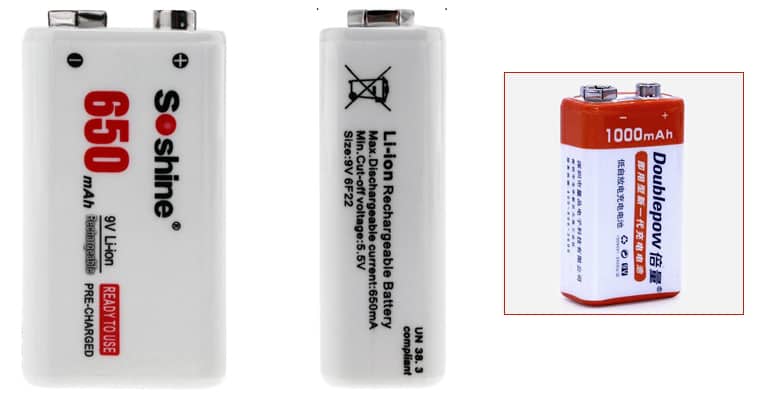
Also see https://www.codrey.com/electronics/9v-rechargeable-battery-right-wrong/, and
https://www.electroschematics.com/battery/
Farther from the basic theme…
Portable task lights and flashlights were early adopters of LEDs, and LED-based devices are now the most prevalent portable lighting solutions available on the market. The addition of a microcontroller to power and manage the LED provides opportunities for control of custom lighting patterns and sequencing, user interface control, and increased to result in longer battery life at greater lumen output. Besides, the microcontroller implementation will not only help to add luxurious features light dynamic focusing, distress alarming, etc. but also to tweak or add functionality via a simple program update versus a costly hardware redesign.
A while ago I decided it was finally time to blend some of my scattered flashlight design ideas into an ‘all things’ flashlight/task light, and so I configured the first version of my flashlight/task light controller module. I plan on putting up a lengthy write up of the weeklong design work but I need to wait until my special test jigs arrive (let’s see what happens). Sad I know, but…
I will be back… …with a fairly serious project to “let there be light”!