A fan failure in today’s advanced electronic projects may result in other delicate and expensive components failing, causing costly repairs and delays. A 3-wire PC fan is an easy and inexpensive way to prevent such a costly disaster as with a 3-wire cooling fan you can monitor the speed at which the fan is running. In order to implement this in your next design, however, you will need a simple ‘fan performance monitor’ circuitry to read the tachometer signal and determine if the fan has failed.
3-Wire PC Fan & Tachometer Signal
Then, as shown below, in addition to the power supply wires, a 3-wire PC fan has a 3rd wire to output a tachometer signal. The connector plug is usually wired so that the Red wire accepts +12VDC input, the Black wire is Ground, and the Yellow wire outputs the Tachometer signal.
The Tachometer signal is derived from a Hall-Effect sensor that senses the rotating magnetic fields generated by the rotating rotor. The hall cell emits a 50% duty cycle square wave pulse train as shown in next figure. On most 3-wire fans, the tachometer output will have 2 pulses per revolution. Note that the final tacho signal is usually an open collector/open drain design that provides the square waveform output. The voltage levels are usually at TTL level (+5 V) through an external pull up resistor, however, this is by no means a rule and there will be exceptions!
How to Handle the Tachometer Signal?
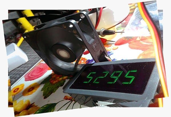
I wasn’t originally planning to try the below mentioned scrap 3-wire fan, but as it’s only available in my junk box I been visualizing the tachometer signal with my oscilloscope just to see the ‘raw’ output.
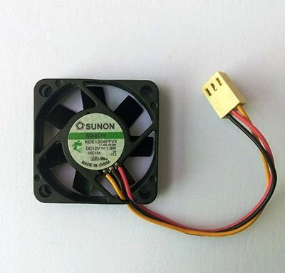
- 3-Wire PC BLDC Fan
- Input Voltage: 12VDC ±10%
- Peak Current (@12VDC): 200mA
- Tachometer Output: 2 pulses per revolution (open-collector/drain output)
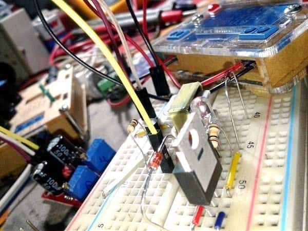
And then what I’ve observed is a clumsy tacho output signal, it’s natural just because there’s no pull-up resistor added at the output. So I added one 10KΩ pull up resistor, and a 100nF capacitor as pointed in the below schematic.
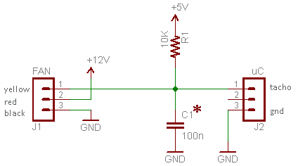
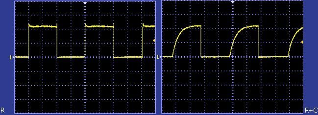
The latter inclusion is because the tacho pulse (Just below 100Hz), was still a bit noisy at that time. With the addition of the capacitor, my tacho signal cleaned up a bit more, but depending on your application, you may need to tinker with that capacitor value. You’re probably going to need an oscilloscope for the measurement, and below you can find two casual snaps captured by my oscilloscope (see the effect of RC filter on square wave rise time – slows it down)!
A good reference on Filters & Wave Shaping: http://www.learnaboutelectronics.org/Downloads/ac_theory_module08.pdf
Well, you can now route the tacho signal output to one I/O on your favorite microcontroller and find out the rotation per minute (RPM) rate of the fan pretty easily. The rough maths for RPM computation is, RPM = (Tacho Frequency/2) x 60, because one full rotation of the fan delivers 2 tacho pulses through its yellow wire.
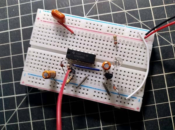
Back to my experiment, I used a cheap digital pulse counter to check the functionality of my ‘fan adapter circuit’ (given before) and got pretty reasonable results.
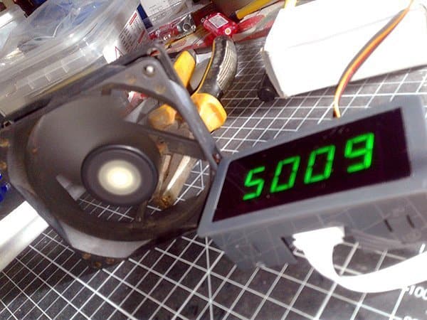
I think it’d be reasonable to guess that one-half of the number of pulses counted in one minute is directly proportional to the RPM rate of my fan as there’re two pulses generated for each revolution. So, turning to the estimated rotation per minute rate of the fan, it’s roughly 2500 RPM at unregulated 12VDC fan supply. The applied division (by two) will be essential hither because the digital counter (actually a pulse per minute counter) will see 2 input pulses in 1 second (~83.5 Hz tacho signal frequency at that time).
Just to make this more clear, recall that a 3-wire fan reports it speed by delivering a tachometer pulse output usually twice per fan revolution. So, with a fan spinning at 3000 RPM, you would measure a 100Hz pulse rate (3000 rev per min / 60 sec * 2 pulses per rev = 100 pulses/sec or 100Hz).
Easy Arduino Digital RPM Counter – DIY
If you want to interpret the tacho output of a 3-wire fan, the most simple and elegant way is the use of an Arduino digital tachometer. I’m ready to explain in simpler terms about building and using a digital tachometer with Arduino which should be sufficient for your application, but recently I posted such a project here in this website. So take a look at that tried and tested project, and make it a good try https://www.codrey.com/arduino-projects/arduino-tachometer/
Fan Performance Sensor (FPS) – Idea For Design
A fan performance sensor is a special circuitry to read the tachometer signal and determine if the fan has failed. Fortunately, it’s easy nowadays to develop an FPS circuitry to monitor the tacho output and detect a fan failure. The output of the FPS can then be hooked directly to a buzzer, relay, etc. Note that, in principle, the FPS output will remain constant until a specified speed level is reached (at that point, the signal output will change to a different state).
Got inspired by a Texas Instruments (www.ti.com) application note, I started the design of an improved FPS circuit by using a dual mono-stable multi-vibrator (one shot) chip. The design is very critical component-wise, thus I need some good luck with it. Since the experiment is in progress, don’t expect anything to be functional or useful now. I’ll post the exclusive project here in due time! Meanwhile, you can refer this old, basic, but adaptable do it yourself project https://www.electroschematics.com/3-wire-cooling-fan-monitor/. And, this one is an adaptable digital pulse counter project https://www.codrey.com/arduino-projects/digital-pulse-counter/
And, the Little Teardown!
Finally I made a moment to dismantle my dusty and rusty 3-wire fan as I’m curious to know what it have in its inside mechanism.
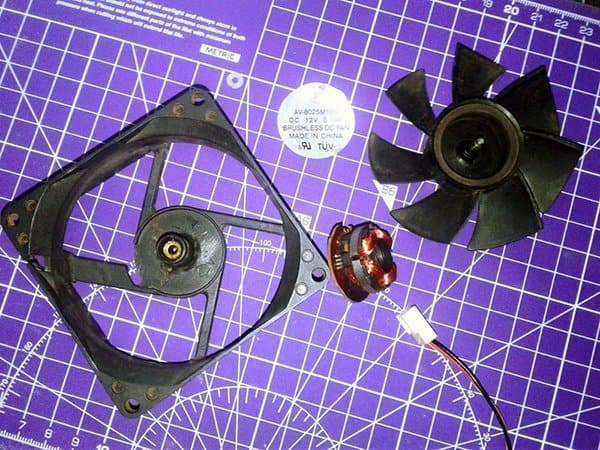
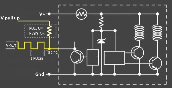
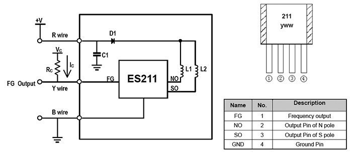
Subsequently, it caught my attention that the 3-wire PC fan is a 2-phase, brushless dc motor, realized with the help of a minuscule driver chip ES211 from InnoSen (www.innosensor.com).
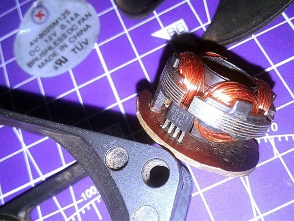
The ES211 is a little 4-pin chip composed of a hall sensor and output coil drivers tailored to drive 2-phase brushless DC motors. For more information on ES211, see its official datasheet https://datasheetspdf.com/pdf/957869/InnosenTechnology/ES211/1.
Following is the application example of the ES211 chip. The red, yellow, and black wires are the input points of the motor system Rc is an external pull-up resistor for the use of measuring tacho signal. In view of the design, the value of the pull-up resistor Rc could be decided by the transistor saturation voltage (Von), sink current (Ic), and off-level voltage (Vc). The formula is Rc=(Vc-Von)/Ic. For example, if Vc=5V, Ic=5mA at 500mV saturation voltage, then Rc=1KΩ.
Oh, I missed that! See, the tachometer signal (tach signal) is also known as “FG (frequency generator) signal”. Tacho signal conveys RPM information in the form of square waves, with a frequency proportional to the rotation of the rotor. That’s all for now. Your comments will be very welcome!
Hi T.K. Hareendran,
Thanks for this post, some info helped me repair my Prusa MK3 part blower. I thought the IC might have died, and put in a donating IC from a totally other old fan.. They both had and IC with the number “211” on it. and following spec sheets it said to support 18-Volt all the way down to 4 volts. It came out of a 12Volt old fan and the blower is 5Volt.
I have orderd new once but I needed it to work ASAP. In the end it did not even turned out to be an IC, but a PCB pad that was broken off form the PCB that I thought I had checked already… >.<
Very helpful!
Thank you.
Chris: Thanks! It makes me so happy you feel that way 👍
Provided some needed insight. Thanks.
Oregon: It’s my pleasure to hear your valuable feedback. Thanks!