You may not know the name of one of the first independent semiconductor designers, but you have encountered Hans Camenzind’s designs countless times.
Incredibly, he created the 555 timer chip alone, spending a year designing it by hand as a freelancer Hans Camenzind.
Here you can see the design concept of a simple electronic latch switch module based on the ubiquitous 555 timer chip. Well, let your memories wake you up!
In principle, a latch switch (latching switch) is a switch that once triggered on remains on until the power that goes into is cycled or removed. The most commonly used latching device in a circuit is the silicon controlled rectifier (SCR). However, the below latch switch module circuit, as said before, employs a NE555N timer IC as the latch controller.
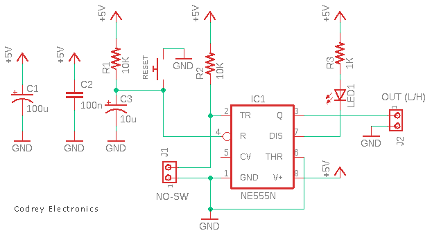
Although it is a bit odd use for a 555 timer IC, it is an easy way to make an electronic latch switch module with that cheap and easy to find timer chip. As you can see above, the core circuit is basically designed to run on a 5V DC power supply.
Working of this little circuit is very simple and self-explanatory. The input connector J1 is provided to connect a normally-open (NO) momentary button switch. In standby state, output of IC1 available through the output connector J2 stays low, as stablished by the R-C network R1-C3 on start-up. The visual indicator LED1 remains lit in this standby state.
But when the switch is closed for a while, the latch is set to a high output state where it will stay even if the switch is returned to its initial position. The resultant high output can then be used to drive an external load, like a buzzer or relay, for example. Note that the push-on momentary switch (RESET) can be used to reset the latch when needed.
Shown below is the internal 555 schematic (from web), along with a quick description of the functions of a few of its pins.
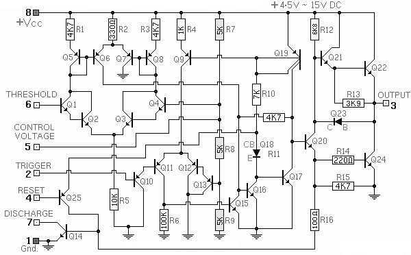
- The Trigger Pin 2 of the 555 is the input to the lower comparator and is used to set the latch, which in turn causes the output to go high
- The Output Pin 3 of the 555 comes from a high-current totem-pole stage made up of a couple of transistors. The output voltage available at this pin is loosely equal to the +Vcc applied to pin 8 minus 1.7V
- The Reset Pin 4 of the 555 can be used to reset the latch and return the output to a low state. The reset voltage threshold level is 0.7 volt, and a sink current of 0.1mA from this pin is required to reset the device
- The Threshold Pin 6 of the 555 is one input to the upper comparator, and is used to reset the latch, which causes the output to go low
- The Discharge Pin 7 of the 555 is connected to the open collector of an NPN transistor, the emitter of which goes to ground, so that when the transistor is turned on, this pin is effectively shorted to ground (Gnd)
I could not have said it better! See this NE555 IC datasheet.
So, this post provides an easy to build and inexpensive circuit for latching electronic/electric devices with a momentary button press that can control a latching external power switch mechanism.
Feel free to use this circuit as is, or modify it for your needs, wherever you might need a simple latch switch circuit. Depending on your application, you may need to replace the default momentary button switch with a mercury tilt switch, a rolling ball tilt switch, a magnetic reed switch, or a vibration/impact sensor.
And as said earlier, to turn this latch into a power switch, its output may be used to control an electromagnetic relay, bipolar junction transistor, or a logic-level power mosfet. Any device from some simple beacon lights to mighty motor horns can then be used as a final output load.
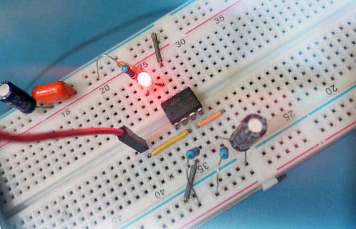
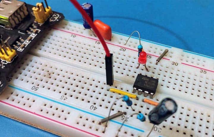
Below is a quick snap of my breadboard test setup. Note that some components such as button switches are not included in the breadboard version, as I used standard breadboard jumper wires to trigger and reset the latch circuit.
Finally, are you afraid to design a new product based on this idea because of the uncertainty of component supply? Go ahead without doubts, the venerable timer chip is still here and will be around for a long time!