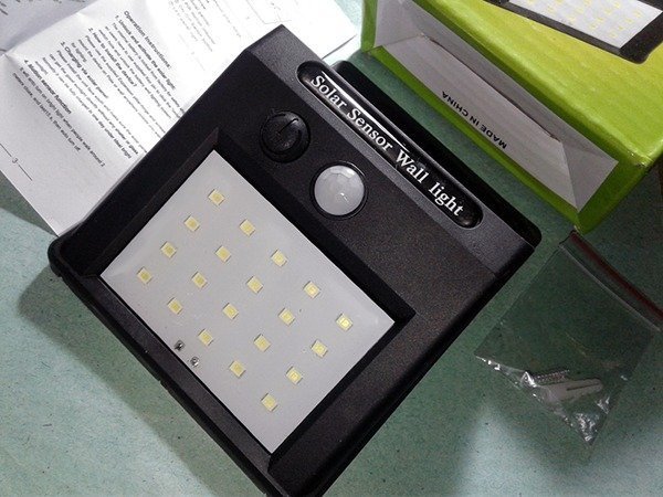
Optical smoke alarms, also known as photo-electric smoke alarms, are particularly useful in bedrooms, lounges, hallways, and in other areas where we can otherwise expect false alarms from the common ionization smoke alarms. An optical smoke alarm have a quick response to visibly smoldering fires, and the optical sensing technology makes it less prone to false triggers from cooking fumes. Here’s another simple circuit of a little optical smoke sensor module suitable for making your own optical smoke alarms using off-the-shelf components.
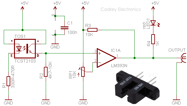
At the heart of the given circuit is a Transmissive Optical Sensor TCST2103 (TOS1), also called as Fork Coupler, from Vishay Semiconductors (www.vishay.com). The sensor includes an infrared emitter and phototransistor, located face-to-face on the optical axes in a leaded package which blocks visible light. Next part is the quite popular dual-comparator LM393 (IC1) configured to switch an external electrical load when its non-inverting (+) input level falls below a certain threshold set by the onboard trimpot (RP1) linked with its inverting (-) input. In the circuit, resistor R1 limits the operating current of the infrared LED inside the optical sensor, while resistor R4 limits the current flow through the alert indicator LED1. And resistor R3 is wired as a pull-up resistor at the open-collector output of IC1. This “active-low” output can be used to control an external electronic circuitry for driving powerful audio/visual annunciators like beacons, hooters, etc.
Keep note, working principle of the optical smoke sensor introduced here is somewhat different from the technique used by most commercial optical smoke detectors. In such a commercial product, an infrared transmitter component intermittently pulses an invisible beam of light into the infrared receiver chamber to check for smoke particles. When a fire breaks out smoke enters the chamber through its opening vents, and its particles cause the light beam to be scattered onto the infrared receiver component. Once the scattered light hits the infrared receiver component, associated electronics circuitry wakes up the alarm system to sound alerting the occupants to the fire.
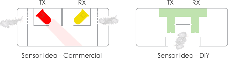
Our circuit can also ‘see’ the smoke indeed. However, with the fork coupler as the ‘eye’, our circuit constantly monitors the invisible light path between the light transmitter and receiver, and climbs an alert only when the light beam is interrupted by dense smoke inside the sensor’s slot.
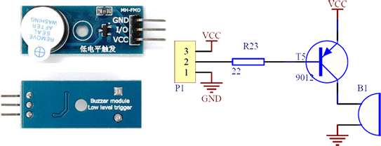
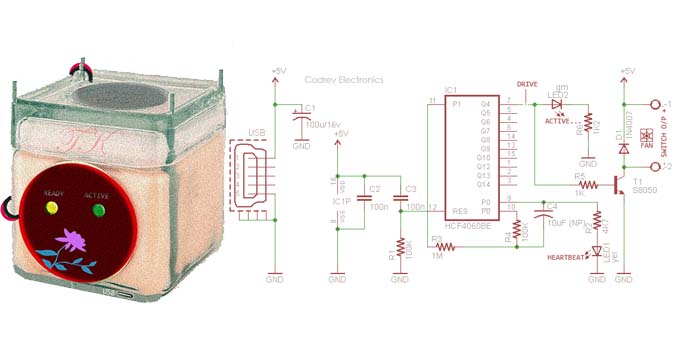
For the impatient, there’re numerous active buzzer modules (see next figure) are now available at affordable rates. Just buy such a type (with active low-level trigger) online, and connect it with the finished prototype to complete the construction of a quick home-made optical smoke alarm.
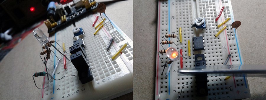
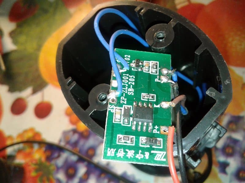
Finally, here is a casual click of the initial experiments from author’s workbench!
Hello! I hope you are ok! Well, I was looking for this masterpiece after all these past 2 weeks tbh. I was asked by my professor about this alarm’s electrical circuit, i’m new in electrical engineering so i was so confused and basically my interest isn’t really in here. But I’m trying my best here. Uhm– And may I ask whether I could use this as reference of my study? I’ll put credit for you. THANKS A LOT! You do save my life! I wish for your reply soon! Thanks
@Sherl: You are welcome! Feel free to use this as a reference for your study.
Nevertheless, I’m grateful to you if you give credit to me (author) and this website (publisher) where it would matter. Thanks very much for your positive remarks!