 I’ve recently completed the basic design of a general-purpose analog constant current generator employing easily available electronics components. This is a simple circuit that is easy and cheap to build and is very useful especially if you want to do experiments with DC halogen bulbs, heater coils, high-power LEDs, etc. Needless to say, I’ll be updating the basic design in the coming days.
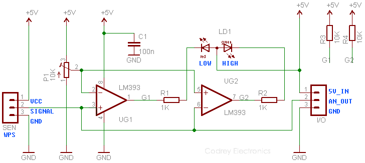
This is the complete schematic (v1) of the analog constant current generator. As you can see, the circuitry and the theory of operation is extremely simple and basic.
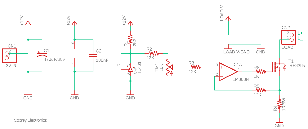
Since this is a standalone constant current generator/dummy electronic load, it’s tailored to work happily with a low-current independent 12VDC power supply. The “power part” of this circuit is a commonly available Power MOSFET – the IRF3205 (T1) – treated as a variable resistor. Note that a Power MOSFET can be also used in a linear (rather than switching) application, and it’s then typically treated as a variable resistor!
IRF3205 Power MOSFET Datasheet https://www.infineon.com/dgdl/irf3205pbf.pdf?fileId=5546d462533600a4015355def244190a
The next key part in this circuit is a TL431A (VR1) three-terminal programmable shunt regulator diode. There’s a low-power dual-operational amplifier chip – the LM358 (IC1) as well.
TL431A Datasheet https://www.onsemi.com/pdf/datasheet/tl431-d.pdf
LM358 Datasheet https://www.onsemi.com/pdf/datasheet/lm358-d.pdf
The working principle of the analog constant current source is straightforward and self-explanatory. When a dc load is energized, a small voltage is developed across the 1Ω power resistor (R4) and is fed into the inverting input (pin 2) of IC1. This positive voltage is inverted by IC1, reducing the voltage at its output (Pin 1) which further reduces the voltage across R4 via T1. This stabilizes the output voltage to the value it seems at its non-inverting input (Pin 3). Any change in current through R4 causes a voltage change at Pin 2 of iC1 which is exactly offset by the negative feedback. The result is a constant current through the power resistor and the connected load.
The reference voltage is around 2.5V, and I used the TL431A (VR1) for the reference voltage generator because that’s what I had on hand. Other ideas of generating a steady reference voltage can be tried, as well. The 10K potentiometer (TM1) in the circuit is for fine adjustment of the current source, and hence a 10-turn multiturn precise trimpot would be better than the ordinary potentiometer used by me. Likewise, you don’t need to use the same IRF3205 MOSFET – any drop-in replacement part can be used if you know what you’re doing there. Below you can see the quick test display of the IRF3205 used by me. Thanks to my “Banggood” component tester!

Now note that when there’s 1A of current flowing through R4, there will be 1V across it. And, the maximum reference voltage IC1 can see will be around 1.2V. As you have might observe, the 2.5V reference is further scaled down by the resistor network R2-TM1 to around 1.2V.
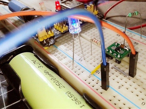
Although I made my quick test version on a mini breadboard, never use a breadboard for your final prototype (one thing that might happen between a breadboard and a printed circuit board is that on a breadboard usually, the parasitic capacitances are higher). It’s worthy now to take notice that it is quite easy to get this circuit to oscillate, which certainly is unwanted and can make it hard to trim the load current accurately. Moreover, the 1Ω power resistor must be able to dissipate quite a bit of power. Also, the power MOSFET must be used with an appropriate TO-220 heatsink.

At first, I tested my breadboard prototype with a white 12V/10W power LED, and the connected oscilloscope shows that there’re no nasty oscillations (yes, my build is stable so far). And then, I assembled the entire circuit on a piece of stripboard – it’s only intended to be a temporary model till I make a PCB, but it actually works well. Trust me, I’ve tested it then up to 12A by using the 0.1Ω/20W old power resistor in lieu of the default 1Ω/5W resistor (see below). As you would expect, I also swapped the heatsink for a beefy one. On paper, the IRF3205 MOSFET can handle 110A of current, we won’t be anywhere near the peak of that hill though!

Now to a few things need to be considered for this design. The first thing is that an independent/separate 12V power supply should be used for the constant current generator circuitry. Next, if you choose to use a different op-amp, then opt for a rail-to-rail op-amp as it would be better than the LM358 op-amp used by me. Also, it’s extremely important to pay close attention to the rating of the components in a power electronics circuit. Wrong or lazy choices can lead to serious disasters such as explosions or fires.
Just remember that you can substitute an analog (or a pulse width modulated) signal for the reference voltage to build a constant current power amplifier (or a digitally controllable electronic load/dummy load). It’s more conventional and easier to understand, so I won’t get into that now. Anyway, in such cases, you can use the unused second op-amp as a unity gain buffer/voltage follower as pointed below.
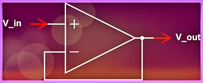
An op-amp buffer, which has an output that exactly mirrors the input, is extremely useful in many situations since it helps to solve the common impedance issues. The input impedance of the op-amp buffer is very high, and the output impedance is very low. So, you can use an op-amp buffer to help link together a sub-circuitry without worrying about impedance problems.
Finally, there is an amazing world outside of your lab window. Never miss it!