There is nothing amazing about looking at the design concept of a simple USB LED lamp, I know. But believe me, the midget USB LED lamp presented here has a little power reservoir in the form of a super capacitor, so it is a bit divergent approach!
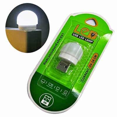
First off note that dirt-cheap Chinese USB LED lamps like the one shown above are widely available everywhere. Although it demands some skills and patience, you can modify the shell of such a moderately sized USB LED lamp to enclose your own electronics.
So, be ready to roll…
Circuit Diagram & Design Description
As mentioned before, the key part in this design is a commonly available “coin cell” supercapacitor. Compared to conventional capacitors, a supercapacitor, also known as EDLC (Electric Double Layer Capacitor) is outstanding for its very high charge storage capacity and very low equivalent series resistance (ESR). Its high cycle life, low charging time and large power output make it an ideal choice for this application.

A notable advantage here is that the power output of a standard USB downstream port is typically 5V/500mA and is fairly stable. This makes the proposed USB charging circuitry of the supercapacitor simple and straight forward.
As I am sure you are aware, a simplest USB-powered circuitry to charge a supercapacitor can be rigged up by just connecting it to the USB power source in the right way. The only other crucial component needed is a diode to stop the supercapacitor from discharging back into the USB port. The diode should have a low forward voltage drop (VF) like a Schottky diode.
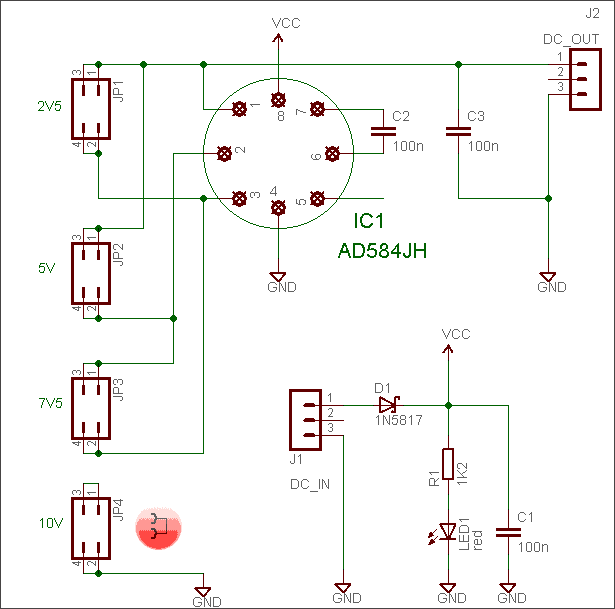
Moreover, a standard USB port is a constant-voltage source so a constant-voltage (CV) charging method is recommended, and this obviously demands a protective resistor in series with the supercapacitor (often it may be necessary to limit the charging current thru a series resistor while charging a supercapacitor with an unprotected power source). So, this is the simplest circuit diagram:
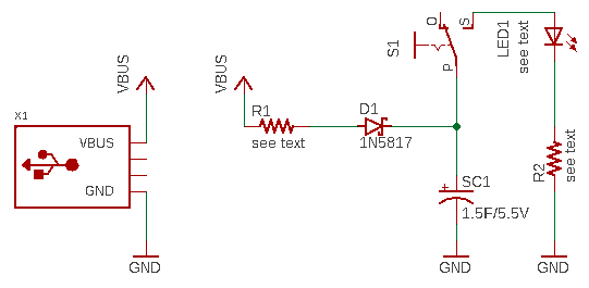
- 1N5817 Datasheet https://www.vishay.com/docs/88525/1n5817.pdf
Note at this point that the energy stored in a supercapacitor can be estimated using the formulas given here https://en.wikipedia.org/wiki/Supercapacitor#Energy_capacity.
Anyway, it is unlikely we can use the stored energy until the supercapacitor is fully discharged. So, the functional energy is more likely to be the difference between the initial voltage and the voltage at which the load stops working (reality will be far from this assumption but it gives a rough idea of the usability and may help with optimizing the final design).
According to some Chinese supercapacitor application guides, formula for calculating the protective resistor value is RP = V1/IMAX – RESR , where V1 is the charging voltage, IMAX is the maximum allowable current, and RESR is the equivalent series resistance (ESR) of the supercapacitor.
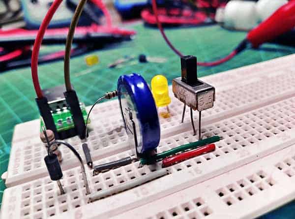
At the moment of this writing, I don’t have any precise instrument to measure the ESR (AC/DC) of a supercapacitor. So, on a rough estimation (but after referring the datasheet of the supercapacitor), a 10Ω ½ W protective resistor (R1) was selected for my quick test setup. Similarly, a regular 5mm amber LED with a 510Ω ¼ W series resistor (R2) was used for LED1. And, this is my quick test setup wired on a regular breadboard:
Now to a slightly more elaborate design idea!
If there is a need to charge the supercapacitor through an appropriate small/low-current solar panel, be prepared to add an active protection system to the existing circuit. This is essential because the power output of a small solar panel is highly variable depending on the lighting conditions. The added active protection system should be then configured to set off when the input voltage of the circuit reaches beyond 5.5V, which is the recommended maximum voltage rating of the supercapacitor. Below is the modified circuit diagram.
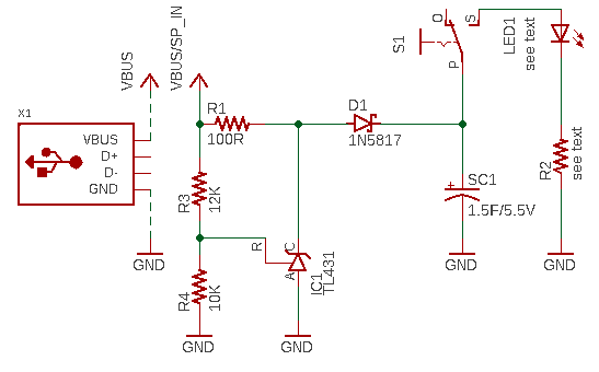
As you can see, it comprises nothing but a belittled circuit centered on the programmable shunt regulator TL431/KA43. Although this idea was also successfully tested on the breadboard, it’s not photographed!
Conclusion
That’s all for now! From here, there is room for several improvements pointed at enhancing the efficiency of the basic design ideas. I will come to that later. Oh, you can do it too!
Related Links