I still believed electronics hobby can be promoted through the application of nostalgic components and circuits. This is a meek try to inspire someone learning and experimenting with basic 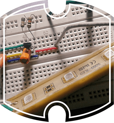 electronics circuits, or to wake up electronics lovers to restart their funny experiments with certain longstanding electronics chips. Well, get ready to build a mighty solid-state LED/Lamp flasher right away using cheap electronics components!
Flashing warning lights are generally used to attract the attention of nearby people to alert them to the situation they are approaching or that is approaching them so that they can take whatever appropriate action is needed.

BJT Astable Multivibrator
The mighty solid-state flasher is in fact a bipolar transistor (BJT) version of an astable multivibrator (AMV) as shown in the below schematic. The astable has two outputs that repeatedly change state at a rate set by the time constants of its feedback network. All circuits related to the project described here will work between 9V and 12VDC, however, 12VDC is recommended for greater reliability. Don’t underestimate the value of this little design as it’s highly flexible, and still useful for square wave and pulse generation!
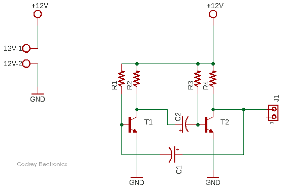
The circuit switches endlessly from one state (T1 on and T2 off) to the other (T1 off and T2 on) and back again at a rate determined by the RC timing components to generate two anti-phase square wave signals, with an amplitude almost equal to the supply voltage – one output is available in this circuit through connector J1.
- T1 & T2 = BC547B
- R1 & R3 = 100K ¼ W
- R2 & R4 = 10K ¼ W
- C1 & C2 = 10uF/40V
As pointed above, the circuit works by alternately charging and discharging cross-coupled capacitors C1 and C2. This results in transistors T1 and T2 turning on and then off in an alternating fashion. The flashing rate can be changed either by adjusting the values of the capacitors and/or the resistors (The frequency output will vary slightly with changes in supply voltage). An asymmetrical waveform can also be produced by using different values for the RC components. Simply, by picking specific values for C1, C2, R1, and R3 (while keeping R2 and R4 relatively low), you can set the speed of your astable multivibrator circuit.
Basic BJT AMV LED Flasher
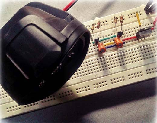
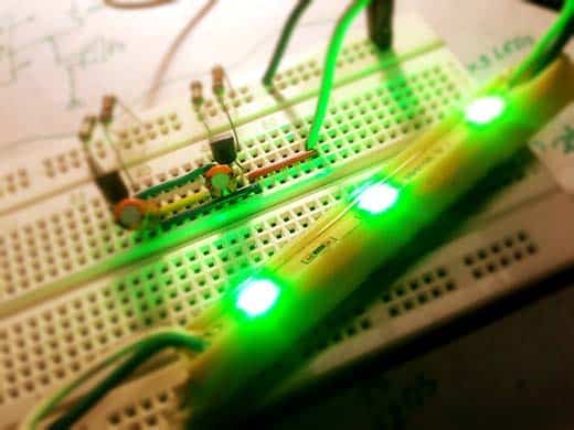
It’s very easy to prototype the circuit on a breadboard. Honestly, I built my first BJT AMV LED flasher using a perfboard back in the 1980’s when I was in school. Recently, for this project, I reproduced the same on the breadboard, and blink a 12V SMD LED stick (Green 5050 LEDs x 3 with a 50Ω built-in series resistor) by wiring it in parallel with the resistor R4 (see below). You can either connect your LEDs in parallel with R2 and R4 i.e. directly to output T1 and T2. With the given values in the first schematic (C1=C2=10uF, R1=R3=100K), the frequency is roughly 0.7Hz. In principle, these symmetric values can produce a square wave of 50% duty cycle, but they do not have to be symmetric.
The astable multivibrator keeps on changing state and generates a square wave at each collector. The frequency of oscillation can be calculated, as the time for the relevant capacitor to charge sufficiently for a change of state to take place will be approximately 0.7CR and, as two changes of state occur in each cycle the periodic time T will be: 0.7 (C1R1+C2R3). If C1 = C2 and R1 = R3 the mark to space ratio will be 1:1and in this case the frequency of oscillation will be: 1/1.4CR.
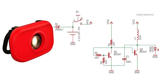
This is the updated circuit diagram of the BJT AMV LED FLASHER (Only one LED channel is shown in the schematic – second is identical. Each channel will flash about 0.7 times per second).
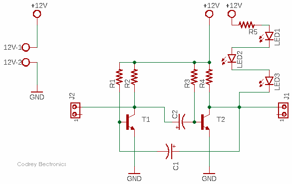
Even for this simple circuit, some calculations are involved to get it right. The LEDs are wired in series, protected by one 100Ω ¼ W resistor (R5). Let’s just assume that the typical forward voltage (Vf) of an ultrabright red LED is 2V at its recommended forward current of 20mA. Knowing these values, we can calculate the voltage across R5, and the current flowing through the LEDs. The 6V (3x2V) across the LED strip leaves 6V for the resistor R5. we can assume that the transistor (T1) induces a voltage drop of approximately 0.7V, so there remain 5.3V for R5. Using Ohm’s law from above, we get 5.3V/100Ω = 53mA, which is quite a lot of current for the LED, but since the LED is flashing, the average current overtime is still low, which makes this an acceptable thing to do.
Next to look at is the power dissipation of the resistor R5. There is Joule’s law which states P = E×I. Now that we know both E and I, we can calculate the heat dissipated by the resistor about 0.3W. This is quite a bit high for a ¼ W resistor, of course, but again, the LEDs are pulsed so that there is not much to fear about.
According to the datasheet, BC547B transistor has a continuous collector current (Ic) close to 100mA, and a minimum dc current gain (hFE) of 200 (Ic = 2mA, VCE = 5V). Good enough for me and you!
Related Datasheets:
BC547B Datasheet https://www.farnell.com/datasheets/410427.pdf
5mm Ultrabright Red LED Datasheet: http://descargas.cetronic.es/WW05A3SRP4-N%20.pdf
The Might LED/Lamp Flasher
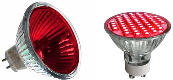
In a mighty solid-state flasher, there are often times when we need to control a high current (or high voltage) using a much lower current or voltage, and this requires some kind of power switching. As an example, my first intention is to drive a pair of 12V/50W red Halogen or red LED bulbs (in parallel) through the mighty flasher.
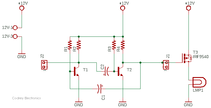
For reliability and ease of control, we really have to choose an electronic power switch, and here a voltage controlled current source is recommended – the IRF9540 P-Channel Power MOSFET (https://www.vishay.com/docs/91078/91078.pdf).
The IRF9540 is a nice candidate as it’s a readily obtainable MOSFET which works up to -100V and with a continuous drain current close to -20A. This is good as we are switching in the high side and have a common ground rail. One general drawback is that a P-Channel MOSFET has a higher on-resistance which will introduce a higher (approximately threefold) power loss of a similar-sized N-Channel MOSFET. Anyway, it does not matter much here, so simply proceed to the below figure, and see its implementation. Remember you may also use the IRF9530 instead, but refer to its datasheet at first (https://www.vishay.com/docs/91076/sihf9530.pdf).
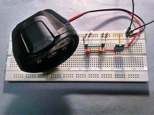
And, see my quick breadboard setup. In order to test the proto, I simply used a 12V LED foglamp at that time!

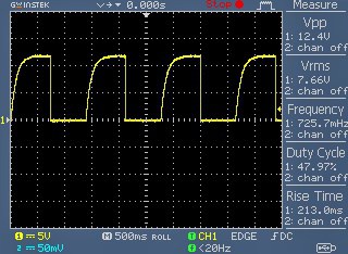
Connecting an oscilloscope to the gate of T3, the result shows a waveform with a duty cycle close to 50% at about 0.7Hz.
As you can see, the leading edge of the output waveform is noticeably rounded due to the charging characteristics of the capacitor in the cross-coupled circuit.
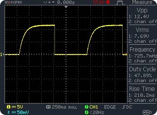
That means the capacitor action slows down the rise in voltage as each transistor turns off, producing the curved rising edges. This is an innate problem with the basic astable circuit, but we can overcome this by a revised circuit – you should be able to do that!
What is pulsing before you?
How does the BJT AMV circuit actually work, and how to gently hone it? If you need an in-depth description of the BJT AMV circuit operation, you can check out this link to read an excellent post https://www.electronics-tutorials.ws/waveforms/astable.html