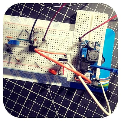
There are different types of cheap Chinese dc-dc buck converter modules. The most popular module still widely available is one with the LM2596S adjustable regulator, it’s a pretty old design, 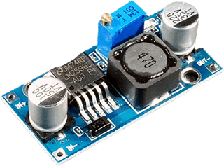 though. You can buy this module from electronics web stores very cheaply. I too have more than a dozen of these blue modules. When using this minuscule dc-dc buck (stepdown) converter modules, it’s important to consider what components are at play and reduce the number of possible causes of catastrophic failures out of the blue. Here’re some quick pointers that will (hopefully) help you get it right!
Impressive claims
According to one eBay seller’s description, the LM2596S Adjustable DC-DC Step-Down Module can step-down the input voltage to a range of 1.25 – 35V at up to 3A (1.5A continuous). Its key features are:
- Compact size
- LM2596S converter IC
- Input voltage range 4.5 to 40V
- Output voltage range 1.25 to 35V
- Multi-turn trimpot for adjustment of the output voltage
- Conversion efficiency up to 92%
- Voltage regulation: ± 2.5%
- Load regulation: ± 0.5%
- Short circuit protection (current limiting)
- Output current up to 3A (additional heatsink is required)
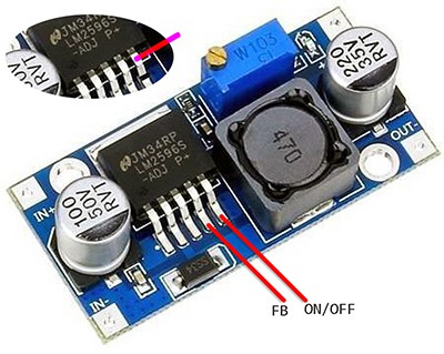
The module itself, true to its word is compact – with input power applied to one end and output power available on another end. With the silkscreen right-side-up, the input solder pads will be on the left side. There is also a large white arrow (conversion direction and polarity) on the back of the module to help you get it right. Turning the trimpot clockwise (CW) increases the output voltage while turning it counter-clockwise (CCW) decreases the output voltage. The lowest output voltage is approximately 1.25V while the upper limit of the scale will rest on the actual input voltage and is typically about 1.5V less than the input voltage.
Electronics insight
According to ON Semiconductor’s (http://onsemi.com) LM2596 datasheet, the LM2596 regulator is a monolithic integrated circuit, operates at a switching frequency of 150 kHz, capable of driving a 3.0 A load with excellent line and load regulation. See its features:
- Adjustable Output Voltage Range 1.23 V − 37 V
- Guaranteed 3.0A Output Load Current
- Wide Input Voltage Range up to 40 V
- 150 kHz Fixed Frequency Internal Oscillator
- TTL Shutdown Capability
- Low Power Standby Mode, 80uA typical
- Thermal Shutdown and Current Limit Protection
- Internal Loop Compensation
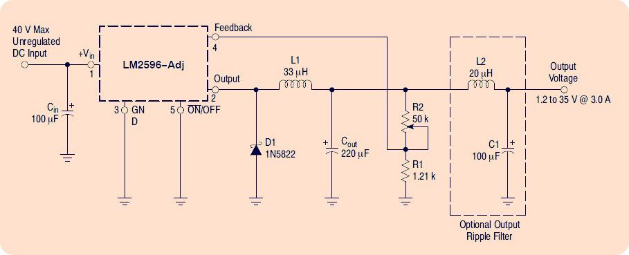
In my module, however, it appears that there’re a couple of disparities to the reference design – slightly different inductor value, capacitor voltage rating, etc. but it’s mostly based on the typical application circuit (shown above). Below is the reverse-engineered basic schematic of the particular LM2596S module I bought from a Chinese online store.
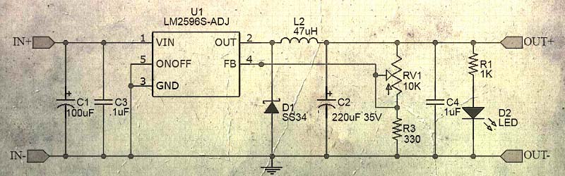
In my module (HW-411) the input capacitor is 50V rated, and the output capacitor is a 35V type. The Schottky diode is SS34, and the inductor is a 47uH SMD.
According to the datasheet, a feedforward capacitor (CFF) is needed in parallel of R2 (here the trimpot) when the output voltage is greater than 10V to ensure stability. But the recommended capacitor is present on my module.
For LM2596, the output voltage is determined by the equation Vo = 1.23(R2/R1 +1). Given the component values used in my module (10KΩ/2 trimpot and 330Ω resistor) the output voltage can be regulated between 1.23V to 20V only. And, certainly, a heatsink is a must for continuous operation at over 1.5A is mandatory.
A quick physical inspection shows the regulator chip at the core is one LM2596S -ADJ with the familiar NSC logo but feels like a counterfeit product – wasn’t NSC took over by TI before a long time?
![]()
Another noticeable thing while referring back to the official reference diagram is the value of the inductor – it’s 47uH not 33uH. Besides, the Schottky diode recommended should have a 3A rating, but looking at the SS34 diode’s dimension it seems like a bogus part rated for 1A only – probably a relabelled SS14 Schottky diode.
Good or Bad?
Honestly, it depends on the design of the module and its supporting components. I did run the same module in a power LED project before a few weeks and found it’s good for that application. So it wasn’t a very bad candidate. Recently I retested one of the modules under various working conditions, measured its efficiencies, and the results recorded. The testing methodology employs my trusty digital variable power supply module and digital dc electronics load module in the usual manner. The efficiency was calculated using the simple formula: (VOUT x IOUT / VIN x IIN) x100, and during testing, it seemed to be close to 70-80%.
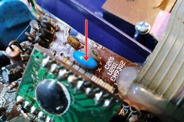
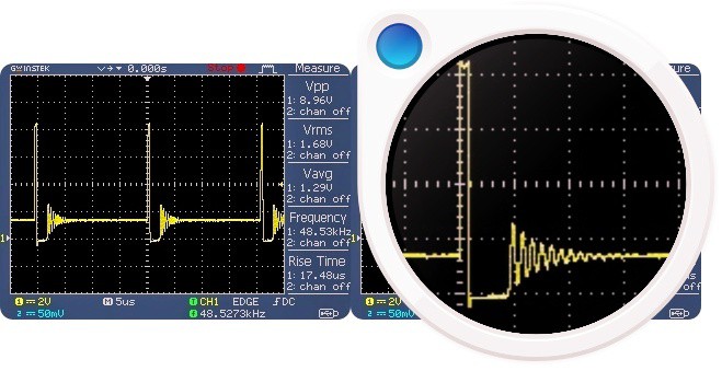
Later, I backed off my DSO and took a number of measurements. Below you can see the waveform available at pin 2 of LM2596S. See, the switching frequency is only 50kHz, not the anticipated 150kHz!
Just a side note: Now I’m reading about fake LM2596 ICs. You can see one post here http://k6jca.blogspot.com/2018/02/counterfeit-lm2596-regulator-boards.html
To sum up, briefly, the LM2596 module is somewhat a good pick, if you’re ready to accept certain issues and limitations. It’s probably going to be best suited for little (low-voltage and low-current) electronics projects, but may not be ideal if you are considering using one in the digital power supply rail of your serious project having a sensitive microcontroller at its core. Yep, it’s certainly not a ‘clean’ voltage regulator module.
Hackable Electronics!
I’m well aware of the new tiny dc-dc buck converter modules having a higher (1MHz+) switching frequency. Even so, I’d like to play with these modules, because there’s an easy way to do some little hacks. To exemplify, I can easily add remote power on/off control feature (Pin 5 hack), and a tricky current limiting mechanism (Pin 4 hack), using a few dirt-cheap components resting all around. There’s nothing wrong with hacking a cheapo Chinese module!
Adding a current-limit feature to a Chinese module that has a suspicious LM2596 chip onboard? Yes, a while ago I saw one LM2596 red module coming with an adjustable current limit feature (http://sparks.gogo.co.nz/catalog/LEDs-272/LED-Drivers-170/Constant-CurrentVoltage-Step-Down-DC-DC-Converter-369.html) but I was not able to get its original schematic diagram. Later, I rigged up a small circuit to do that, and it worked right. The typical approach is to apply a voltage to the feedback input from an output load current sensor circuitry. In a future post, I can share more thoughts on this current-limit hack. So, stay here to get exclusive updates!