Wikipedia says Current Limiting is the practice of imposing a limit on the current that may be delivered to a load to protect the circuit generating or transmitting the current from harmful effects due to a short-circuit or overload. And, Foldback is a current limiting feature of power supplies so that when the load attempts to draw overcurrent from the supply, foldback reduces both the output voltage and current too well below the normal operating limits. Under a short circuit, where the output voltage has reduced to zero, the current is typically limited to a very small fraction of the maximum current.
The prime purpose of foldback current limiting in linear power supplies is to keep the output transistor within its safe power dissipation limit. A linear regulator dissipates the difference between input and output voltages as heat. Under overload conditions, the output voltage falls and so the difference becomes larger, thus increasing dissipation. But, foldback helps to keep the output transistor within its safe operating limits under fault or overload conditions. Foldback also significantly reduces the power dissipation in the load in fault conditions, which can reduce the risks of fire and heat damage (https://en.wikipedia.org/wiki/Current_limiting).
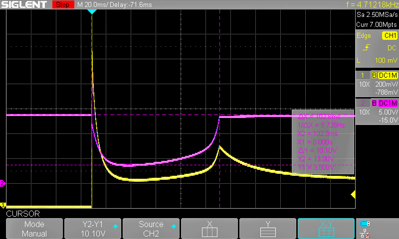
This little post will shed some light on the secrets of current foldback and current limiter circuits. Before going further, however, just take a moment to study the below oscillogram which shows a bench power supply current limit circuit operate on the inrush surge of a small incandescent lamp. Lamp current is in yellow (2A/div approx.) and the power supply voltage is in pink (5V/div).
For a fraction of a millisecond, the lamp attempts to draw about six times its steady-state current. The overcurrent protection circuit of the power supply dropped the output voltage from 13.9V down to about 3V to limit current and protect the power supply. After about 100ms, the foldback current limit circuit resets and the voltage returns to full value – a small extra surge of lamp current occurs when the voltage is restored, then the lamp slowly returns to its steady-state current draw of 2.3A. Thanks to https://handwiki.org/wiki/Engineering:Foldback_(power_supply_design).
Also, in this post you can see how to build a crude current limiter
Current Limiting & Foldback Current Limiting?
What’s the real difference between current limiting and foldback current limiting?
It’s utterly simple! Current limiting is the maximum current that a voltage regulator will pass before shutting down. This may be a built-in feature of some voltage regulators (tracking regulators and some others have a dedicated current sense terminal).
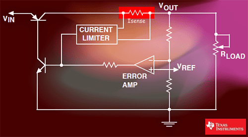
The common practice is that the output current is passed through a small value ISENSE resistor (current sensing resistor). The current sensing resistor is then determined by something like 600mV/Imax so that when the voltage drops across the sense resistor approaches 600mV, a blocking transistor is activated to throttle the current.
The foldback current limiting (sometimes referred to as re-entrant current limiting) is similar to current limiting, but here when the limit is crossed (or in case of a short-circuit that reduces output voltage to zero), the current is foldback to a value less than it would deliver under the normal load condition.
Now note that voltage regulators which are relatively high current types usually use a current limiting mechanism where the maximum allowable value of load current is dependent on the input-output voltage differential across the part. The reason this is crucial is due to a characteristic of all transistors called Safe Operating Area (SOA) that limits the amount of current a transistor can safely handle as the voltage increases.
Also, it’s worth noting that a foldback limiting circuit, which’s rather different from constant current limiting, has some hysteresis built into it. As the load resistance decreases to a point where limiting occurs, the output voltage can drop suddenly from the nominal voltage to a much lower value. That’s okay but returning the load resistance back to the value where limiting started may not restore the output voltage to nominal, that means, the load resistance may have to be increased to a higher value to allow the regulator to return to constant voltage operation. I hope you get it now!
One of the major advantages of the foldback-current limiting scheme is that it actually reduces the current through the pass transistor once maximum load current is reached (the pass transistor is only warm to the touch thus obviates the requirement of a beefy heatsink).
It should be noticed that foldback current limiting should not be specified for switch-mode power supplies as it’s not essential for protection of the supply and is prone to severe application problems such as lockouts. For this reason, constant current limiting is usually preferred in switch-mode supplies, whereas foldback current limiting is in linear power supplies. However, in practice, any load (often nonlinear loads, problems can occur with linear resistive loads, though) that demands a heavy inrush current when it’s switched on initially may be subject to lockout when foldback current limiting is used.
So, when summed up, a current limiting circuit, as the name suggests, throttles the current from a regulated (mostly linear type) power supply to a maximum amount determined by the circuitry, and in this way, serious damages to the electronics, both the power supply and the load being powered can be avoided. There’re two basic types of current limiting circuits most commonly used in linear regulators viz. Constant Current Limiting & Foldback Current Limiting.
Employing a constant current limiting scheme, the output voltage is maintained as the current increases until the maximum set point is reached. At this point, the current is held at that level whilst the voltage across the load is reduced. On the other hand, in the foldback current limiting scheme, the output voltage is maintained until the point where the current limiting starts to come into action. From that point, rather than just limiting, the current actually starts to scale down. That’s it!

For further learn before delving into practical circuits:
- https://www.torexsemi.com/technical-support/tips/foldback-circuits/
- http://power-topics.blogspot.com/2008/09/over-current-protection-in-power.html
- http://powersupply.blogs.keysight.com/2013/01/types-of-current-limits-for-over.html
- http://www.industrial-electronics.com/switching-power-supply_1-14.html
- https://e2e.ti.com/blogs_/b/powerhouse/posts/ldo-current-limit
- http://www.industrial-electronics.com/electrnc-dvcs-9e_17.html
Linear Voltage Regulator with Foldback Current Limiting!
The basic concept of a linear voltage regulator with a foldback current limiting circuit is depicted here.
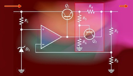
In this circuit, the voltage drop arose across the current sensing resistor R4 by the load current must not only get over the base-emitter voltage (Vbe) required to turn the transistor Q2 on, but it must also surmount the voltage across resistor R5. That is, the voltage across R4 must be: VR4 = VR5 + Vbe.
During an overload (or short-circuit) condition, the load current increases to a value that is enough to cause transistor Q2 to conduct. At this point, the current can increase no further. The fall in output voltage results in a proportional decrease in the voltage across resistor R5 thus, less current through resistor R4 is required to maintain the forward-biased condition of transistor Q1.
Still on the subject but let me show you a compact linear regulator module, the CJMCU-3042, based on the high-performance low dropout linear regulator LT3042.
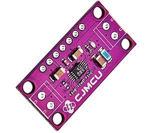
The LT3042, designed especially for powering noise-sensitive RF applications, has a number of built-in protection features that include reverse battery protection, reverse current protection, internal current limit with foldback and thermal limit with hysteresis. The internal foldback current limit starts to decrease the current limit at VIN – VOUT > 12V. For more information https://www.analog.com/media/en/technical-documentation/data-sheets/3042fb.pdf.
Wrapping Up
In many linear voltage regulator applications, the normal operation power dissipation in the pass device can easily be multiplied by a factor of ten or more when the output is shorted. This may destroy the pass transistor, and possibly the regulator unless the heat sink is outsized to handle the fault condition. A foldback current limiting circuit reduces short circuit output current to a fraction of the full-load output current thus avoiding the need for a heavy heat sink.
In the foldback current limiting scheme, a fraction of the output voltage must be used to oppose the voltage across the current limit sense resistor. Current limiting does not occur until the voltage across the sense resistor is higher than the opposing voltage. When the output is grounded, the opposing voltage is no longer present so current limiting occurs at a lower level. An in-depth explanation can be found in this (a bit old) application note of LM125 (https://shrubbery.net/~heas/willem/PDF/NSC/AN/AN-82.pdf).
That’s all for now. Stay tuned for the upcoming part of this post packed with do-it-yourself project ideas!
Thanks
Analog Devices
Texas instruments
American Society for Engineering Education
Thanks very much it so helpful
@Mathew: I’m so glad it’s helpful. It’s an honor!