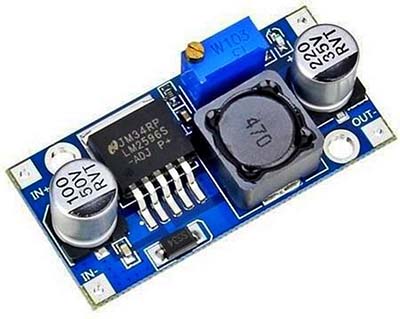
I have a great collection of cheapo Chinese DC-DC stepdown converter modules that I use for everyday purposes in my lab. Most are the good old but still popular LM2596S modules available under $1 from most online storefronts. The module is a constant voltage (CV) buck (stepdown) converter switching power supply where the output voltage is set by a multi-turn trimpot.
Last week, I wanted to use one of these LM2596S modules to drive some low voltage power LEDs and laser diodes using 9-12V DC power supply sources. The particular module can be used only in CV mode, but I needed a current limit/constant current (CC) feature too for certain reasons. After a thorough Googling, I found that there’re some tricks to do that. For the hack, one external output/load current sensor circuitry is necessitated. So, I then quickly rigged up a little circuit to play with the CC idea. This is the basic circuit diagram of that constant current adapter (subject to revision).
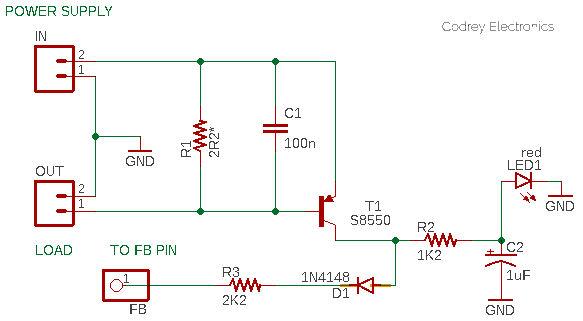
As you can see, this is a very simple piece of electronics configured to be seated in the middle of the entire setup. That means the load (OUT) gets its power supply from the LM2596S module (IN) through the adapter circuitry. The adapter then monitors the load current and gives feedback (FB) to the feedback input (Pin 4 of the LM2596S IC) to govern the load current within predefined limits.
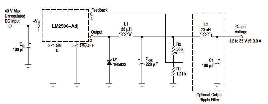
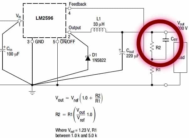
Very simple and handy, indeed! But how this works? In the LM2596-ADj datasheet, you can see its typical application example (see below). In the application example, R1 and R2 forms a divider to send a feedback voltage to the LM2596’s feedback pin. If the feedback voltage is >1.23V, the output is too high and the LM2596 lower the output until the feedback reference voltage reverts to 1.23V. So, we can do trickery by simply injecting the current there to reduce the output at the over-current limit. If so, the LM2596 will then think the output is too high and lower the output voltage instantly.
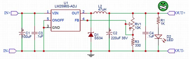
Although the LM2596S module closely follows the same application example, there’re some clear aberrations – you can see them all in the schematic diagram of the Chinese LM2596S module given below.
Back to my adapter design, the key component is a current sense resistor R1. By inserting a current sensing resistor between the load and the module’s output, we have a way to measure the current to the load. The 2.2Ω resistor will set around 700mV across it at 330mA current. When the current value is greater than the threshold level, the transistor T1 will direct a control voltage to set the feedback pin above its reference voltage. The LED1 in the schematic is a mere system indicator, and the capacitors C1 and C2 are elective stabilizers.
The single S8550 transistor circuit can effectively handle the assigned task. With 3.0V input, anode of the 1N4148 diode (D1) can see around 2.3V, and at the final end of the 2K (or 2K2) resistor R3 will see around 1.6V which is above the reference voltage of 1.23V thus the LM259S in the module brings the output voltage down which also lowers the current. This crude idea has been tested successfully with diverse LM2596S modules made by Chinamen.
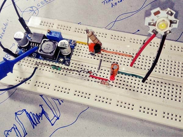
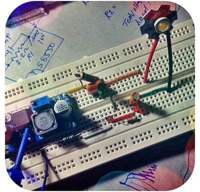
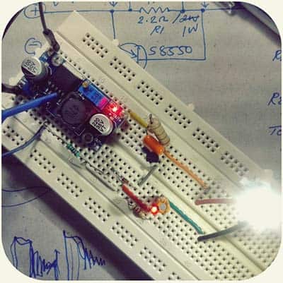
Well, so now you too have a little circuit to add current limit feature in a LM2596S dc-dc buck converter switching regulator module. My first test was with a standard 1W white LED on breadboard, and it worked as expected.
The rest is just laying out the electronics on a suitable proto-board, certainly not on a breadboard! I like to place the LM2596S module on the same proto-board rather than suspending it on the air. I also have a plan to refine my rudimentary design (shared here) by using one op-amp and a handful of some other supporting parts. I expect to be posting the revised project in the future and it being on a customized PCB makes all easier. I hope this thought-share will be beneficial to you. I also hope to learn from your experiences and comments!
LM2596S Module Cheats!
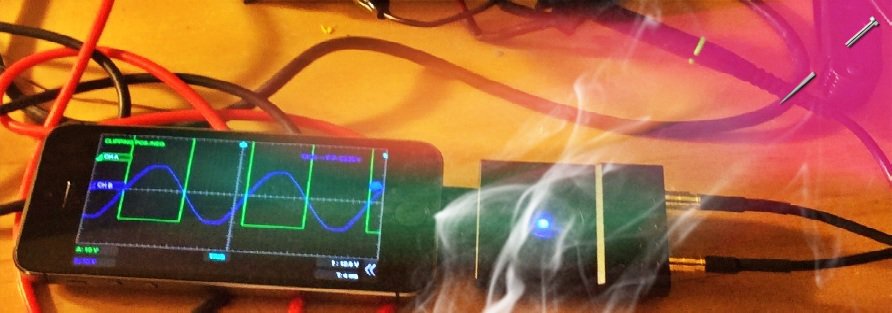
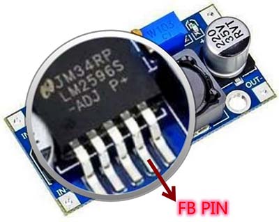
If you’re lucky enough to have one oscilloscope handy, then do probing your LM2596S module to test its switching frequency. Probably you’ll get a shocking readout close to 50kHz from pin 2 of the LM2596S IC!
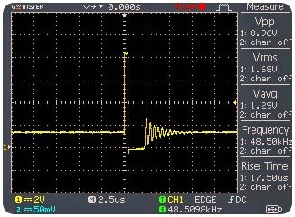
Nothing uncommon – Chinese makers are using counterfeit ICs simply marked as LM2596S! Probably yours’s a clone of the LM2576-ADJ re-labeled as LM2596S -ADJ. The switching frequency of the LM2576 is around 50kHz, vs 150kHz for the LM2596, making it easy to catch on your oscilloscope. Next perceptible thing is the value of the inductor, 47uH inductance instead of the recommended 33uH. I see now that there is a lot of variation in the module here. There are at least three different boards i have seen now. Also, mine doesn’t have the feed-forward capacitor (CFF), which might need in parallel to the top feedback resistor if the output voltage is greater than 10V to ensure stability (refer TI datasheet). I would not recommend using those bogus LM2596S modules with a continuous load of more than 1A, also for loads demanding more than 9V.
Finally, in order to use the adapter circuit in real world, first off calculate the requisite load current to set the value of the current sense resistor using Ohm’s Law. Then power up your whole setup without connecting the load, and adjust the output voltage to the needed value with the trimpot of the LM2596S module. At last, connect the load, and take a test run. Become aware of the intrinsic voltage drop across the current sense resistor. You might consider setting the input voltage slightly above to compensate that, but most loads work fine with a bit lower voltage.
And there you have it! You can try this adapter circuit together with your LM2596S module to drive little power LEDs, charging small batteries and supercapacitors, etc. Odd things, in good hands, often bring the maker to the top!