After some successful experiments recently, I was convinced that measuring current with a WCS series current sensor is easy and straightforward. It’s a cakewalk – after connecting the WCS current sensor’s pins in series with the current path we plan to measure, and powering the sensor up through an appropriate dc voltage, we can monitor/measure the current at ease, whether its is dc or ac.
The real purpose of this article is to introduce you to one WCS series current sensor through a simple do-it-yourself project. This time my choice is the WCS2702 current sensor, and the proposed project is the construction of a little electronic fuse. Well, let’s get started!
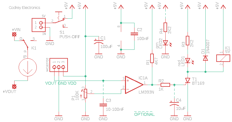
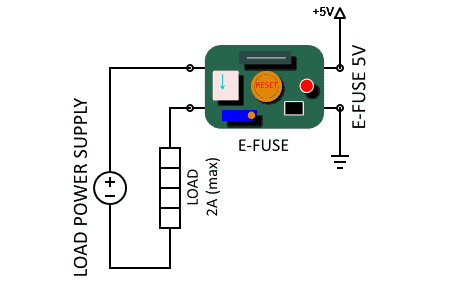
This is the scheme of the little electronic fuse:
Keep the circuit in hand for some moments as I would like to say a few words about the WCS2702 current sensor used at the core of this design.
The WCS2702 AC/DC linear current sensor consists of a precise, low-temperature drift linear Hall-sensor IC with temperature compensation circuit and an electrically-isolated current path with 98mΩ typical extremely low internal conductor resistance.
The applied current flowing through the 98mΩ conduction path generates a magnetic field which is sensed by the integrated Hall-sensor IC and converted into a proportional voltage (1.0mV/mA). The WCS2702 has a wide operating voltage range (3-12V), and a reasonable bandwidth (10kHz). The minimum sensing current is 0-2A at 5V supply.
Read its datasheet http://www.winson.com.tw/uploads/images/WCS2702.pdf
I’m sure you now have an idea of how the above-given scheme works. That’s great! Now let’s examine the rest of the design.
The next part is nothing but a crude voltage comparator built around the quite popular LM393 dual-voltage comparator IC. The output pin (VOUT) of the WSC2702 is routed to the non-inverting input (Pin 3) of LM393’s first comparator (IC1A). And, the inverting input (Pin 2) of IC1A is linked to the wiper of a 100K multiturn trimpot (P1) which helps to set the desired trip-level.
The output of IC1A – Pin 1 – is used to control a small thyristor BT169 (T1) so that it can control the electromagnetic relay (K1) used for switching the final load on and off. This relay is unenergized during normal (not tripped) operation. If the load current exceeds the preset threshold supply, the system will trip and latch the energized relay to interrupt the current flow through the connected load. The trip-state is announced by the red indicator LED1.
The Push-OFF momentary switch (S1) in the circuit must be pushed to release the tripped electronic fuse. The green LED1 is only a power status indicator used to notify you that the electronic fuse system is active. The optional capacitor C3 is recommend to reduce the output noise of the WCS current sensor. Similarly, the next optional capacitor C4 can be added if required to “stabilize” the sensitive gate of the BT169 thyristor.
Frankly, this is a small electronic fuse circuit with a maximum DC tripping current close to 2A only. Note that the typical “zero-current” VOUT of WCS2702 is ½ Vcc, that means 2.5V here, thus limits the threshold level setting middlingly!
But for most hobby-level projects, this “children’s” circuit would be a sensible choice to add overcurrent/short-circuit protection. This electronic fuse can be set up to trip at a very specific current, and if it’s exceeded the relay will disconnect the load. Ideally, the “fuse” will remain open, and importantly not closed again when the load current falls to zero. The fuse is reset simply by pushing the reset switch down. Note that the electronic fuse requires an auxiliary power supply (5VDC), and as long as the power is available, the fuse is ready to operate!
This electronic fuse, of course, can be simply connected between the load power supply and the load – see the overall wiring pointer provided below.
- LM393 Datasheet https://www.ti.com/lit/ds/symlink/lm393-n.pdf
- BT169 Datasheet http://www.unisonic.com.tw/datasheet/BT169.pdf
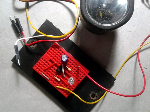
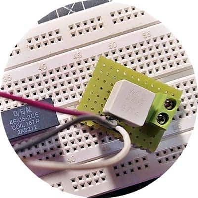
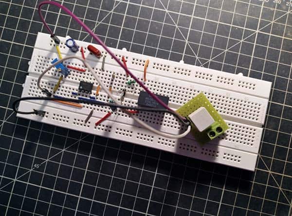
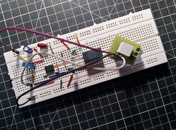
Below are my breadboard snaps. As usual, the breadboard setup has been extensively tested and succeeded!
Next Step…
This little design idea arguably also has a few more disadvantages such as having more terminals and requiring auxiliary power to operate. So, I’m planning to design and build the next version of this electronic fuse, possibly with some added features including:
- More precise current limit set
- Adjustable delay & response time
- Auto-Reset (auto-retry) & Self-Protection
- Enable Input to turn on/off the device
- Inrush current limiter & Voltage Clamp
That’s all for now. Does this project spark your interest? Let me know. Also, if you have any questions or comments, or concerns, put them in the comments below.