This post is just an introduction to how Arduino can be used with synthesizers. So, lower your expectations first, this is not ready-to-go do-it-yourself project documentation. Still interested? OK, get ready to move on!

What’s the hell is a Synthesiser?
As you can read in Wikipedia (https://en.wikipedia.org/wiki/Synthesizer) synthesizer is an electronic musical instrument that generates audio signals. Synthesizers generate audio through methods including subtractive synthesis, additive synthesis, and frequency modulation synthesis. These sounds may be shaped and modulated by components such as filters, envelopes, and low-frequency oscillators. Synthesizers are typically played with keyboards or controlled by sequencers, software, or other instruments, often via a musical instrument digital interface (MIDI).
In principle, almost every synth(synthesiser) is made up of 4 key segments – an oscillator, filters, low-frequency oscillators (LFOs) and an ADSR (Attack, Decay, Sustain, and Release) envelop.
These definitely confuse beginners, I know. But I will not attempt to demystify them now as an in-depth explanation is beyond the scope of this little post. Anyway, you can see a rich explanation here https://www.musicianonamission.com/what-are-synthesizers/
What can an Arduino do there?
Maybe you have a good familiarity with voltage-controlled modular synthesizers. In early modular synthesizers, each synthesizer component, such as an LFO, can be connected to another component by means of a patch cable that transmits voltage. Changes in that voltage cause changes to one or more parameters of the component.
The concept of CV (control voltage) is fairly standard on analog synthesizers. The CV/gate (control voltage/gate) is an analog method of controlling synthesisers, drum machines, and other similar equipment with external sequencers. The control voltage typically controls pitch and the gate signal controls note on-off.
History says so since the publishing of the MIDI standard in 1983, usage of CV/gate to control synthesizers has decreased dramatically. However, CV/gate is very easy to implement and it remains an easier alternative for homemade and modern modular synthesizers. Also, various equipment, such as stage lighting, sometimes uses a CV/gate interface. Further reading https://en.wikipedia.org/wiki/CV/gate
Not to mention, understanding CV is the key to mastering the modular synthesizer. Note that CV allows you to sweep filters, alter pitch, change volume of oscillators – all you need is a bunch of patch cables and some know-how.
Nevertheless, now is the time to take a clear revision! So, get back to the basics, learn some modular vocabulary and learn how to use CV. I did a lengthy Google search (for you) and found this link of a worthy CV primer https://rolandcorp.com.au/blog/aira-control-voltage
At this point, note that you can simply build a crude synth adapter using an Arduino and a few other discrete components. Let me go straight to it.
Arduino Synth Adapter/Sawtooth Wave Generator!
Let’s return to the prime theme. Okay, now you can simply start the experiments by uploading the below code to your Arduino Uno R3 (or Nano v3).
#define sig_output 5 // Signal Output Pin D5
int pulse_width = 0;
int pulse_width_step = 1;


void setup() {
  pinMode(sig_output, OUTPUT);

}

void loop() {
  analogWrite(sig_output, pulse_width);
  pulse_width = pulse_width + pulse_width_step;

  if (pulse_width == 256) {
    pulse_width = 0;
  }
  delay(4);
}
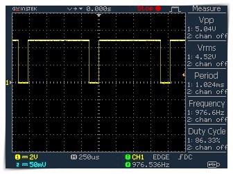
This code will give you a square wave output through D5 pin of your Arduino Uno/Nano. Since the D5 PWM I/O is used here, the frequency will be around 980Hz (see the randomly captured oscillogram below).
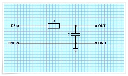
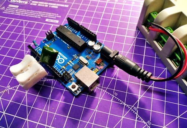
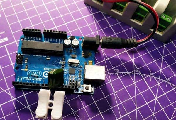
And then, you can add an RC low pass filter (RC LPF) at the output as shown below. This is to make a sawtooth wave from the square wave signal. As you’re aware, making a sawtooth wave out of a pulse width modulation (PWM) signal merely involves passing the PWM signal of varying duty cycle through an appropriate low pass filter (LPF). Keep note this as a starting point for your LPF cut-off frequency calculation – the lower cut-off frequency will give you less distorted final modulation signal while the higher cut-off frequency, the more distorted signal.
Now I can get to the point of this post. My intention was to see if I could generate a sawtooth wave from a single digital/PWM output of an Arduino Uno/Nano to use with a voltage-controlled modular synthesiser. That simply means, prepare the microcontroller to periodically generates a pulse, of which the width can be varied under software control. The Arduino PWM signal generation itself is implemented with “analogWrite()” and “delay()” functions, though there’re better ways to do it.
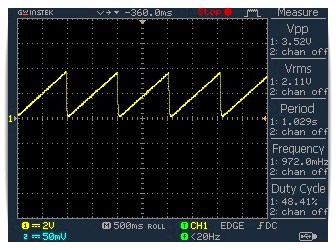
And now there’s indeed a sawtooth, but as you can see the waveform is not a rigorous one. Not a serious matter at this time – if nothing else, it’s very close to 1Hz (ha ha)!
This is what the resulting waveform after the LPF looks like (again, a random scope capture). This was generated with a 100K resistor (R) and 100nF capacitor (C) because it’s what I have around.
To get a sense for how the LPF interacts with the PWM, it is useful to read this post https://provideyourown.com/2011/analogwrite-convert-pwm-to-voltage/
The last piece of hardware to add
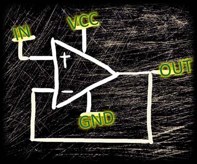
Connecting your Arduino’s output directly to the input of a “strange” device might not be a safe thing. So, try to add a unity-gain buffer built around a rail-to-rail op-amp in between them. You can use the LMV321A operational amplifier here (https://www.ti.com/lit/ds/symlink/lmv321a.pdf). Or, go for a similar op-amp – no problem.
Next design steps & Things to do later…
Voila – the pretty straight basic idea of the low-frequency oscillator (LFO) is fine so far (do let me know in case of any query in the comment box below). My next plan is to implement the waveform generation and low pass filter ideas in a different way to get better outcomes. For those analog synth adapter/module experiments I might choose Raspberry Pi instead of Arduino, as well. Stay tuned to see what’s going on!
Essential Reading: