Nowadays, if you want to build your own digital weight scale, it’s surprisingly easy because you only need a handful of commonly available components in addition to your favorite Arduino microcontroller board. In this primer I’m going to describe how to interface one inexpensive Load Cell to an Arduino Uno with the help of the popular HX711 module so that you can rig up a complete digital weight scale later. Let’s start!
Hardware Required
- Arduino Uno
- 50kg Half-Bridge Load Cell
- HX711 (Weight Sensor Amplifier + 24 bit ADC) module
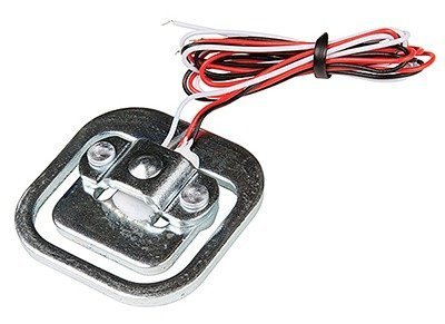
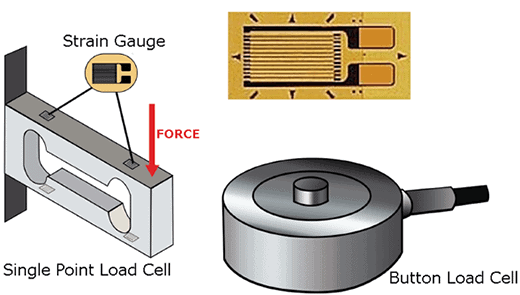
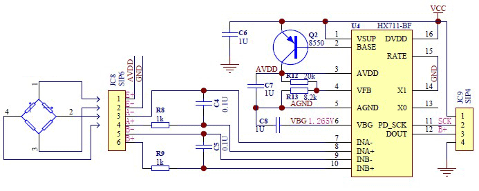
The 50kg Half-Bridge Load Cell (sometimes called a strain gauge) consists of a metallic half-bridge connected to three wires of different colors (red, white, and black). When pressure is exerted on the half-bridge, it sends the corresponding signal via the red wire. This particular load cell can measure weights up to about 50kg.
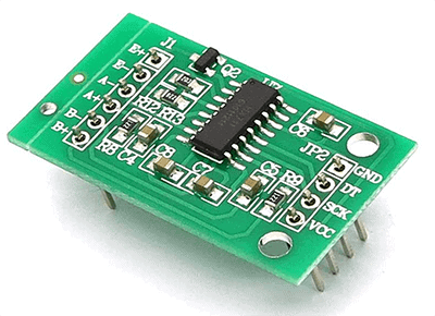
The HX711 module based on HX711 consist of an amplifier and a precision 24-bit analog-to-digital convertor (ADC) designed for weigh scale applications to interface directly with a bridge sensor. HX711 module operates at 5V and the communication is executed through a serial (clock-data) interface.
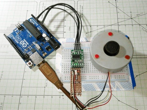
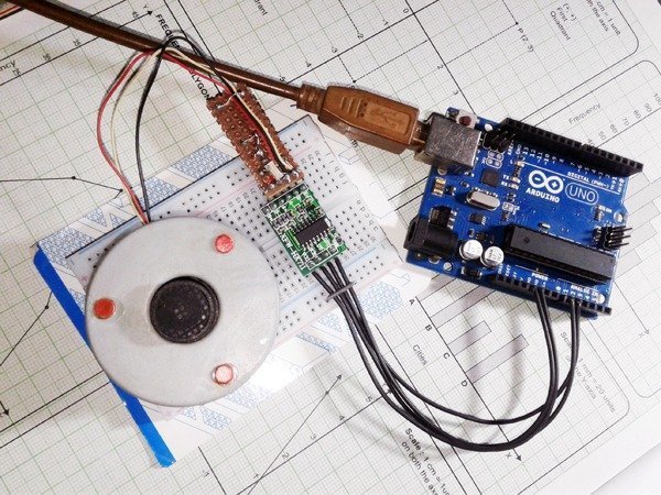
Hardware Setup
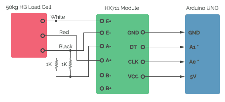
As you can see here, the hardware setup is pretty straight forward. Since the load cell is a half-bridge type, you need 2 external resistors (1Kx2) to attain full-bridge measurement scope.
Software Tryout
After the completion of hardware system you can experiment with example code(s) to verify your hardware setup so that you can proceed further with sureness thereafter. First of all you need to download and install a special library prepared for HX711 (https://github.com/bogde/HX711). After installing the HX711 Library you can upload the well-commented example code (shown below) to your Arduino, as usual.
/*
  Setup your hardware and start the sketch without a weight on the scale
  Once readings are displayed place a known weight on the scale
  Press +/- or a/z to adjust the calibration_factor until the output readings match the known weight
  Arduino pin A0 -> HX711 SCK
  Arduino pin A1 -> HX711 DT
  Arduino pin 5V -> HX711 VCC
  Arduino pin GND -> HX711 GND
*/

#include "HX711.h"

#define DOUT A1
#define CLK A0
HX711 scale(DOUT, CLK);

float calibration_factor = 1025; // see notes
float units;
float ounces;

void setup() {
  Serial.begin(9600);
  Serial.println("HX711 calibration sketch");
  Serial.println("Remove all weight from scale");
  Serial.println("After readings begin, place known weight on scale");
  Serial.println("Press + or a to increase calibration factor");
  Serial.println("Press - or z to decrease calibration factor");

  scale.set_scale();
  scale.tare();  //Reset the scale to 0

  long zero_factor = scale.read_average(); //Get a baseline reading
  Serial.print("Zero factor: "); //This can be used to remove the need to tare the scale. Useful in permanent scale projects.
  Serial.println(zero_factor);
}

void loop() {

  scale.set_scale(calibration_factor); //Adjust to this calibration factor

  Serial.print("Reading: ");
  units = scale.get_units(), 10;
  if (units < 0)
  {
    units = 0.00;
  }
  ounces = units * 0.035274;
  Serial.print("Grams: ");
  Serial.print(units);
  Serial.print("  Calbr: ");
  Serial.print(calibration_factor);
  Serial.println();
  delay(500);

  if (Serial.available())
  {
    char temp = Serial.read();
    if (temp == '+' || temp == 'a')
      calibration_factor += 1;
    else if (temp == '-' || temp == 'z')
      calibration_factor -= 1;
  }
}
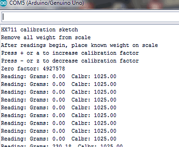
If everything is perfect, you will get a serial monitor window similar to the one shown below (but it won’t make much sense until you calibrate the system)!
Once you’re sure about the functionality of your experimental setup, you can adjust the scale factor with a known weight until you get correct readings (the weight/load needs to be applied to the tip in the middle of the sensor for accuracy). Literally, the example code has auto & manual calibration features i.e. initially auto calibration will run and thereafter you can tweak the values through manual calibration. The given example code lets you to add (+/a) and subtract (-/z) calibration factor value (it’d be better to follow the steps in the code for scale calibration).
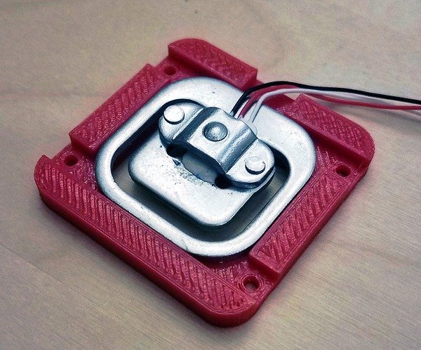
Remember, this article is just a primer that only shows you how to connect a load cell to Arduino with the help of an interface circuitry (perhaps, the fastest method to hook everything together and see if it would work and use serial monitor for readout). So, you must start your own research to complete your digital weight scale concept/project. Also note that, load cells comes in various form factors/specifications, and their wire color codes could be dissimilar than the one mentioned here. Actually, I began working with another (TEM01052B) 50kg half-bridge ‘bathroom scale’ load cell (with one home-made support holder) because a consignment was delayed by the Xmas bang!
What’s a Load Cell?
In principle, load cell (made by using an elastic member with very highly repeatable deflection pattern to which a number of strain gauges are attached) is usually an electro-mechanical a sensor/transducer that converts a load/force acting on it into an electronic signal. Although there are many different kinds of load cells, resistive load cells (and capacitive load cells) are the most popular ‘common’ types widely available now. In a resistive type load cell, if a load/force/stress is applied to it, there’s a change in its resistance, and this change leads to a change in output voltage when a input voltage is applied. “Single Point Load Cells” are broadly used to build scales as they offer excellent off-center loading compensation, but “Button Load Cells” are compact and easy to use and ideal for measuring compression forces that are applied axially.
Since the mV range output from a load cell is not large enough to be processed accurately, one needs to amplify the signal carefully to obtain a utile output. And, the interface usually has a 24-bit ADC in addition to the required regulator and amplifier circuitry (reference – https://www.loadstarsensors.com).
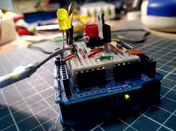
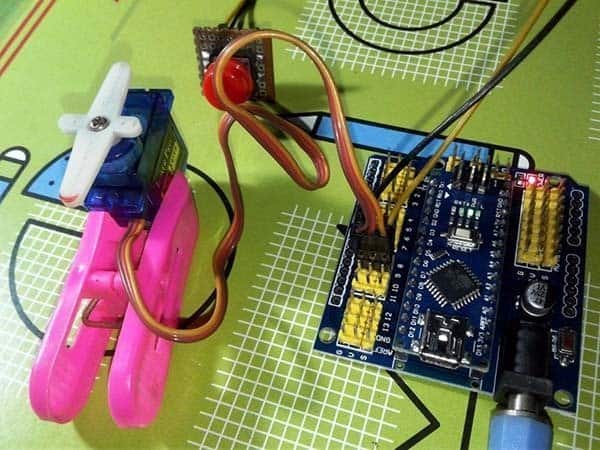
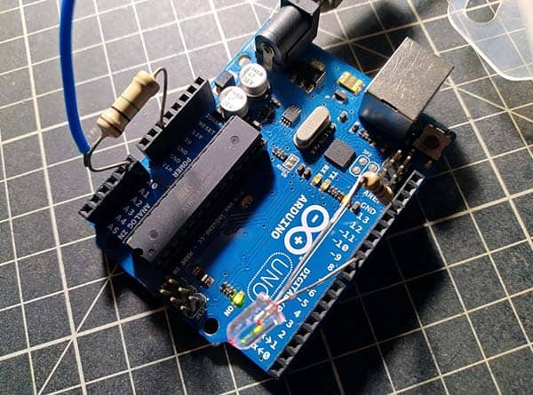
Finally, a bunch of images for your reference:
CAN I GET THE SOURCE CODE FOR CONNECTING THE LCD MODULE TO UNO MODULE. MONITORING THE WEIGHING SCALE READING ON THE LCD MODULE.
George Varughese: Not tried yet! However, you may Google this to get numerous project ideas. For example https://create.arduino.cc/projecthub/embeddedlab786/arduino-based-digital-weight-scale-475032