Quadrature Encoder is a familiar everyday sensor in robotics world. A quadrature encoder is a handy rotary encoder that let you know the speed and direction of a rotating shaft or linear motion. Let’s start with the technical details of a most popular quadrature encoder LPD3806-600BM-G5-24C AB which is a two-phase linear incremental optical rotary encoder available under $10.
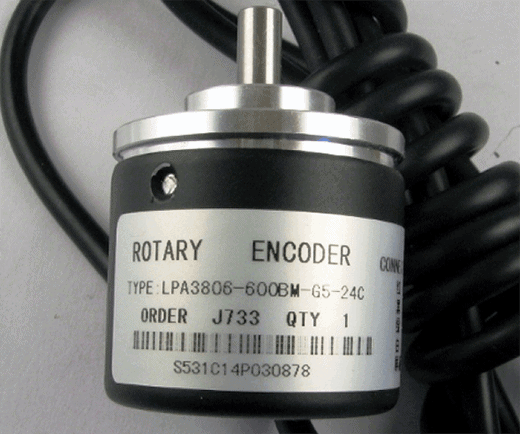
This rotary encoder (like its counterparts) has two outputs each of which will produce digital pulses per revolution. These output pulses follow a particular pattern (usually 90 degrees out of phase) that lets you see which direction the rotation, and by measuring the time between pulses (or the number of pulses per second), you can also derive the speed of rotation. Below is a list of key electrical specification, as provided by www.made-in-china.com
- Resolution (PPR): 600
- Cable length: 1.5M
- Operating voltage: DC5-24V*
- Maximum current consumption: 40 mA
- Maximum response frequency: 30 KHz
- Maximum mechanical speed: 5000 rev / min
- Integrated speed: 2000 rev / min
- Rise / Fall Time: 200ns (Line driver output)
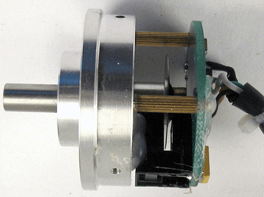
Here’s its inside view. Actually not much there to see – just a shaft-mounted encoder wheel, an optical fork sensor assembly, and a round circuit board with necessary electronics. That’s all.
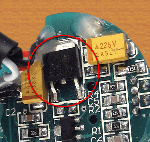
One thing I noticed in the PCB is the presence of a 78M05 3-pin 5V linear voltage regulator chip that caters stable dc supply for the rest of the electronics circuitry. Because of this I’m sure there’s an anomaly in the electrical specification i.e. the minimum operating voltage required is just above 7V, not the indicated 5v!
Next, a few words about the 2-phase output of generic rotary encoders. In a standard rotary encoder there’re two sensors (optical/magnetic) to output two 90° out of phase square wave signals. The reason for having two outputs (A&B) is that apart from the basic speed of rotation measurements, we can also determine the direction of rotation by monitoring the patterns generated by the two output signals. Depending on the hardware configuration, and direction of rotation (CW & CCW) we can expect A and B as depicted below.
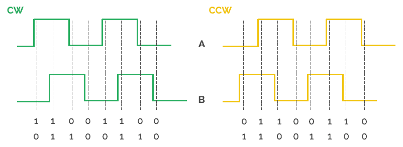
And, the binary pattern is either:
00 = 0
10 = 2
11 = 3
01 = 1 , 0r
00 = 0
01 = 1
11 = 3
10 = 2 . Get me? It’s called a quadrature encoder because the two signals are always in one of four states!
Often, a pauper views this quite differently from me. He may prefer to build his own rotary encoder rather than buying an expensive (or hard to acquire) product for his homely robotic project. Luckily, it’s not very hard as anyone with little skill and patience can easily rig up a rotary encoder from discrete parts laying around. Let me show some diy ideas related with the electronic portion of the rotary encoder in the main.
Optical Fork Sensor
Let me start with the idea of combining a common optical fork sensor with an encoder wheel to build a simple rotary encoder for robotics applications. Optical fork sensor used here is the TCST1103 transmissive optical sensor, and the slotted encoder wheel is a 30mm outer diameter one with 8 slots to provide total 16 transitions. This photo-electric setup works well up to 1KHz (1000 cycles per second).
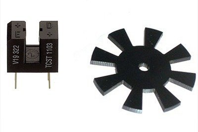
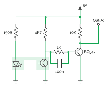
Schematic of only one channel (A) is given here as the second is identical. The circuit should be powered by a regulated 5V dc supply.
CMOS Quadrature Clock Converter
Second option is the use of LS7084 or LS7184 CMOS quadrature clock converter ICs from LSI Computer Systems, Inc. Quadrature clocks derived from optical/magnetic encoders, when applied to the A and B inputs of the LS7183/LS7184, are converted to strings of Up Clocks and Down Clocks (LS7183) or to a Clock and an Up/Down direction control (LS7184). These outputs can be interfaced directly with standard Up/Down counters for direction and position. Following is the typical application circuit for LS7184, adapted from its official datasheet (document# 7183/84-011309-1).

Keep an eye on the MODE (Pin 6) of LS7184 in the above schematic. MODE is a 3-state input to select x1, x2 or x4 resolution so that the input quadrature clock rate is multiplied by factors of 1, 2 and 4 in x1, x2 and x4 mode, respectively, in producing the output UP/DN clocks. The x1, x2 and x4 modes selected by the MODE input logic levels are as follows:
- Mode 0 = x1
- Mode 1 = x2 (default, here)
- Mode Float = x4
Also note that the resistor connected between the RBIAS (Pin 1) and GND (pin 3) sets the output clock pulse width (Tow). With 100K resistor, it’s around 2 us.
Next Idea?
Frankly, I was looking at how to build a cheap yet precise rotary encoder, and I ended up with a small stepper motor based one that made the concept quick and easy. After made a few more thorough tryouts I’ll try to publish one microcontroller based DIY project here. Stay tuned!
Finally, I’d like to extend sincere thanks to my friend “miceuz” of “wemakethings” as I learned many things from his experiments. He’s the maker of “Chirp Plant Watering System”, and I got free samples from him before years. See my featured (good old) hands-on review here: https://www.electronicproducts.com/Internet_of_Things/Sensors/Hands_on_review_making_an_open_source_soil_moisture_alarm_go_full_IoT.aspx
re LPD3806-600BM-G5-24C AB
Made in china displays your personal details PUBLICLY on their site – they say so!!
Also, when i clicked on “leave a message” Malwarebytes blocked a Trojan from them.. BAH!