For a long time I’ve been wanting to use elegant spotlights in my workshop, and although I have a few issues to take care of, like a simple model and a way to install it, the main thing holding me back is budget!
A while ago, I came across a few cheap LED spotlights from Philips India and thought it was worth buying one to test out ideas. The one I bought is the Philips Astra Spot, sold by Flipkart.
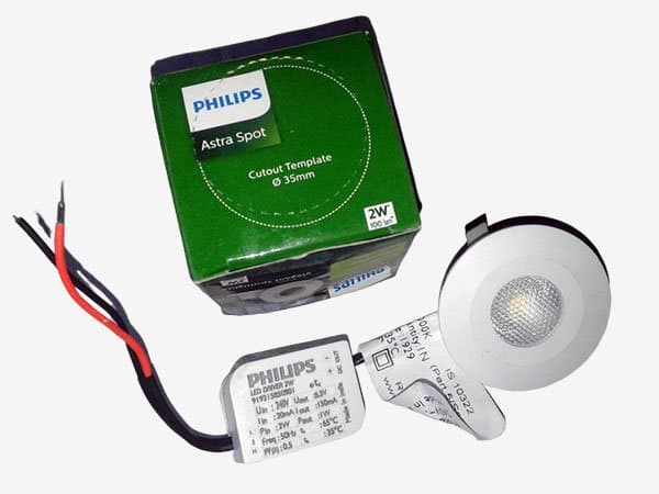
The label on the top of the driver module that comes with the spotlight says it’s rated for 240V AC. The light is rated for 2 watt and will apparently output 100 lumen. The color temperature is 3000K. Yup, the warm white, what I’d normally go for. Anyway, have to take them at their word on this as I have no way to take an in-depth test. Following is the denoted specs of my Philips Astra Spot LED spotlight in hand. Note that the driver is connected to the lamp via a sturdy cable so the two were integrated perfectly.
| LED DRIVER | LED SPOTLIGHT | |
|---|---|---|
| INPUT VOLTAGE | 240VAC /20mA | 6.5VDC/150mA |
| OUTPUT VOLTAGE | 6.5VDC/150mA | |
| INPUT POWER | 2W / PF 0.5 | |
| OUTPUT POWER | 1W |
First off, I made a simple test run, and this is the quick test report prepared with the help of one pocket power analyzer. The power factor (PF) value is a bit suspicious but I still trust my tester. Besides, a word on the light output – it’s way too amber, but for my intent it’ll be right.
- Input Power (@230VAC/50Hz): 1.6W
- Input Current (@230VAC/50Hz): <10mA
- Power Factor (@230VAC/50Hz): 0.85
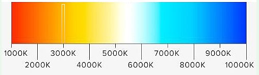
Here note that today’s lamps are usually designed to emit beams whose hue ranges from 2700K to 4000K. The value of 2700K is considered to be warm, 3000 K is considered neutral, whereas 4000K is considered cold white light. Daylight color has a value of 5000 K.
At this point, you’re probably inquisitive what the hell “Power Factor”. I am oversimplifying, Power Factor (PF) of 1 means no power is wasted. Power Factor has always been a tricky concept to explain. Therefore if you retrieve nothing else at the end of the day, just look here https://www.luxreview.com/2016/05/03/two-minute-explainer-power-factor/
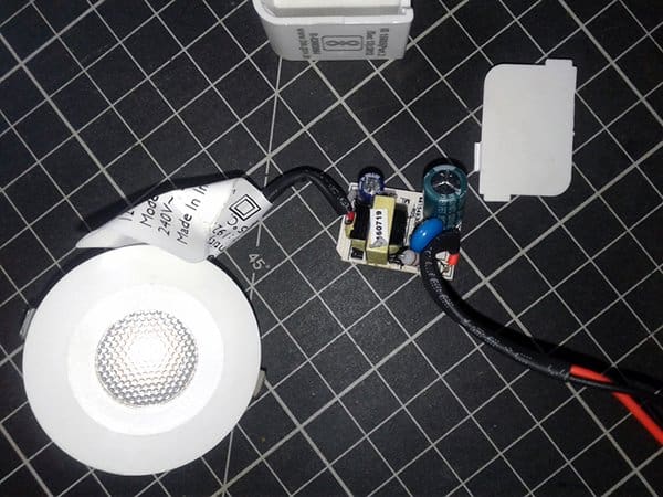
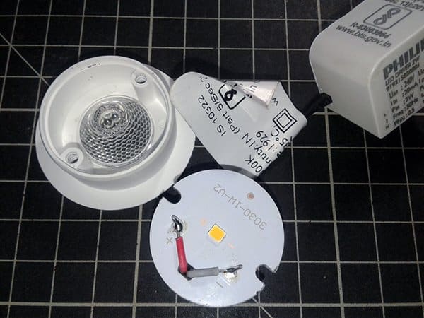
Now the teardown time! Removing the back plate of the driver module shows what I expected, a small PCB populated with a few discrete electronics parts atop.
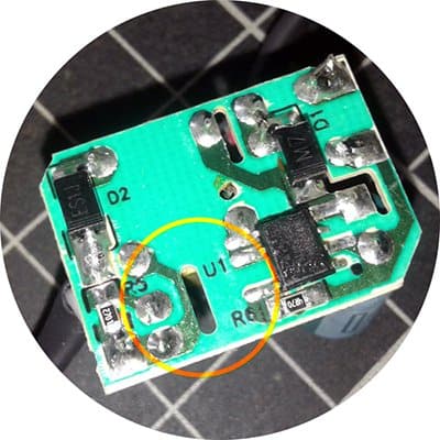
And a driver chip surrounded by some support components at the bottom. All are SMDs.

The internal construction is average. The input and output wires are barely soldered to the circuit board. There seems to be a good attempt at isolating the input AC supply from the output DC supply, and indeed a simple multimeter test confirmed that. Moreover, there’s a marginally fine ‘galvanic isolation’ gap on the circuit board (see below).
The isolation gap on a power PCB is usually a slot cut in the PCB to separate the safe low voltage side from the dangerous high voltage side (that means to provide galvanic isolation in which the two isolated circuits work together but without a direct conduction path). Dimensions of the physical separation is defined by safety agencies and varies with the end application. Again, a tricky topic to explain, so you may go through this link to get a rough idea about PCB clearance and creepage rules http://blog.optimumdesign.com/clearance-and-creepage-rules-for-pcb-assembly
Back to the teardown story, a close inspection revealed that the driver circuitry is centered on BP3166B, which’s a high precision PSR constant current LED driver chip from Bright Power Semiconductor (www.bpsemi.com). As you’re aware, an LED driver is an electrical device which regulates the power to the LED. The LED driver responds to the changing needs of the LED by providing a constant quantity of power to the LED as its electrical properties change with temperature. The common market LED driver is divided into two kinds according to the driving mode – first is the constant current drive, and the next is the constant voltage drive. Here, the BP3166B is a constant current driver with an integrated 650V power MOSFET, and is designed to work in discontinuous conduction mode. There’s a bit more to it than that, but that’s the gist of it.
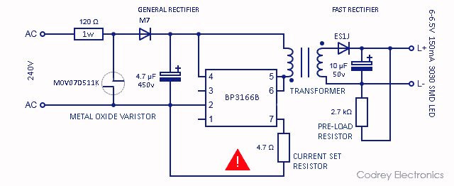
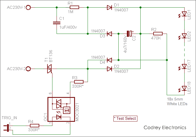
Following is a well-annotated schematic of the above-mentioned LED driver used in my Philips Astra Spot. As usual, it’s formulated by me through physical inspection, but provided without any warranty!
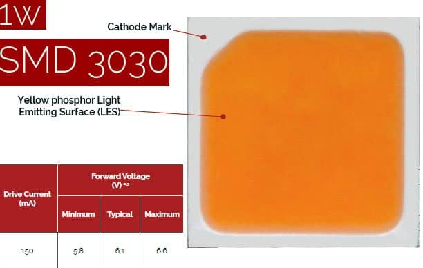
The LED used here is one 3030 SMD LED (6-6.5V/150mA). The image below show the LED chip and the optical materials. The thin white disc at the bottom of the spotlight enclosure is actually the rear part of the LED plate. I’m sure the 6-6.5VDC input is too high for a common white LED. But after a bit of Googling I’ve been able to find dual junction chip LEDs that are basically two LEDs integrated in one package. I think the clever trick is done to get a higher power rating without needing a higher current driver. Yes, now I know what’s actually situated inside the high voltage 1W chip LEDs.
This is the quick description of a cheapo 3030 SMD 1W LED Chip, provided by an esteemed supplier from Shenzhen, Guangdong, China.
You can download the PDF datasheet of another 3030 SMD 1W LED via this download link https://www.mouser.in/datasheet/2/363/STW8C2SA[1]-221927.pdf
I mentioned before that the LED driver is a constant current buck converter. Looking through the schematic, if you look attentively, you can see how the circuitry drives the LED. If it’s a bit new for you, don’t worry, I’ll give you a brief explanation. Let’s see a snip of the BP3166B datasheet, at first.
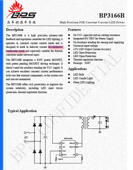
As clearly pointed in the datasheet, the driver chip operates in constant current mode and is designed to work in inductor current discontinuous conduction mode, especially suitable for flyback convertor under universal input.
Now keep note that in discontinuous conduction mode (DCM), which is common in DC-DC converters, the inductor current falls to zero level (in continuous conduction mode, the inductor current in the energy transfer never reaches zero value). Generally, DCM is advised for primary-side regulation because it offers very precise output regulation. To achieve high power factor and low total harmonic distortion (THD), constant on-time control usually is adopted for DCM Flyback converter with fixed switching frequency. It’s assumed that DCM is a cost-saving measure for cheap LED drivers, and DCM in the flyback is to support light load conditions and ensure efficient operation. If you want to learn more about related techniques, then start your day with this blog post https://www.planetanalog.com/power-factor-correction-principles-in-flyback-led-driver/
Should you buy one?
Yes. If warm white light output isn’t an issue for you, and you’re willing to spend some money on nice materials, then maybe. For what you get, I think manufacturer set its price moderate, but even for that price it’s a pass unless the features tightly fit your application. I still love it, though, and hope to keep it working for long time!
I just want to share this additional info with curious readers!
As far as I’m aware, the optics used here is the TIR lens which works on the principle of total internal reflection (TIR). That means when light reaches an interface between two materials with different refractive indices and the correct angle of incidence, there is a bending of the light ray from its original path (refraction). Further reading https://www.ledil.com/support/guide-to-tir-lenses/
Could you count the quantity of turns of the transformer? I am want to make a cheap lamp on BP3133, and too lasy to calculate the transformer.
@Mikhail: Haven’t tried it yet and don’t want to try anymore.
It seems you can buy cheap ready-made BP3166 modules from many Chinese stores. Hope this post helps to some extent http://kuriyan60.blog.jp/archives/31434614.html