If you’re in a plan to make a minuscule robot, you’ll then need to learn more about a coreless motor. I came across it as a pretty great solution for an upcoming healthcare electronics project.
What’s a Coreless DC Motor?
Coreless Dc motor is a special type minuscule DC motor which provides many advantages over the traditional iron-core DC motors. Coreless DC motors are often used for highly dynamic movements. The compact design of coreless DC motors lends itself to applications that demand a high power-to-size ratio. Moreover, coreless motor designs are an especially good answer for battery-powered devices as they draw extremely low current at zero-load conditions. Their ability to manage quick, dynamic moves makes them ideal for use in robotic applications and medical applications.
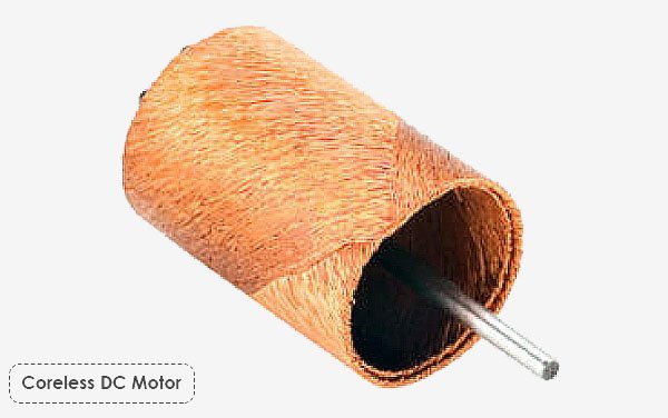
In coreless DC motors, the rotor windings are wound in a skewed (or honeycomb) fashion to form a self-supporting hollow cylinder. The stator is made of rare earth magnets and sits inside the coreless rotor. Here, precious metal brushes are paired with precious metal commutators or sintered metal graphite brushes with copper commutators. The former method is employed often for low-current applications, while the latter technique is more appropriate for applications requiring higher power and current. If you find yourself in need of more details, this is a must-read https://www.motioncontroltips.com/what-are-coreless-dc-motors/
About my quick pick
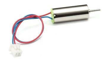
I’ve seen many coreless dc motor pop up on Chinese web stores and desired to give it a good try but it never got to the top of my bucket list until I recently started playing with some healthcare and medical electronics projects. Finally, a pair of coreless dc motors (and matching props) comes in a cute little box. Thanks to the store owner!
According to my seller’s description, the small coreless dc motor is mainly for use in small scale aircrafts. Below you can see its key specifications. Incredible, isn’t it?
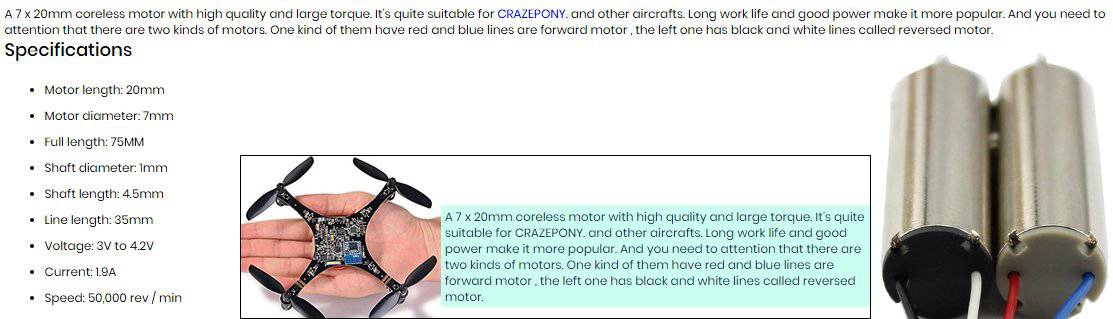
Yes, it’s incredible that such a small motor can provide an RPM around 50000 at 3.7V!
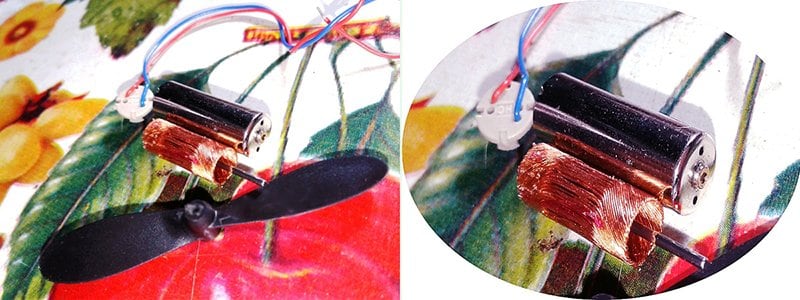
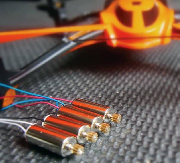
Since I wanted to see what’s inside, I decided to take apart one motor into its constituent pieces. Breaking it apart carelessly with the blade of a small screwdriver, however, resulted in some irreparable damages, meaning the endcap can’t be put back together rightly. Anyway, you can see the rotor in the below image.
It’s observed that usually coreless motors for drone applications comes as a ‘ready-to-use’ pack which includes a set of four coreless motors. Each pack contains a pair of clockwise and counterclockwise hyper-speed motors. Motor rotation and power supply polarity is indicated by the wire color: clockwise: red +, blue – / counter clockwise: white +, black – (don’t run them in reverse). Operating voltage of such a common ‘aircraft’ coreless motor usually lies in 1.5 to 3.7V range, and the load current scale may raise up to 3A. Thanks to www.rc-drones.com
How to drive a coreless motor?
Coreless motor is in fact a brushed dc motor so a complex driver circuitry is not very essential to control it. Now I’ve a couple of cheap coreless motor bought with thoughts of using them in the drive system of my next healthcare electronics projects. Coincidently, several social media followers of mine were asking about how to control common coreless motor speed for their simple projects.
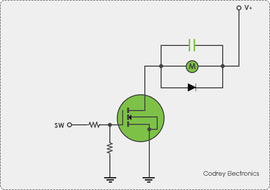
If I’d been building a coreless motor driver circuit, I’d probably have started by using a generic logic-level power MOSFET to switch the coreless motor on and off (see below). I know, the same setup can later be used to regulate the motor speed through pulse width modulation, perhaps commanded finally by a small microcontroller.
Following is a revision of the basic idea shared above. In this revision, an optocoupler is employed to galvanically isolate the input side of the motor driver circuitry from its output side. This is because the coreless motor might draw a lot of power and is electrically noisy, it must be separated from the logic electronics. The basic idea remained intact i.e. use a logic-level MOSFET to turn the coreless motor on and off, with pulse width modulation to regulate its speed if necessary.
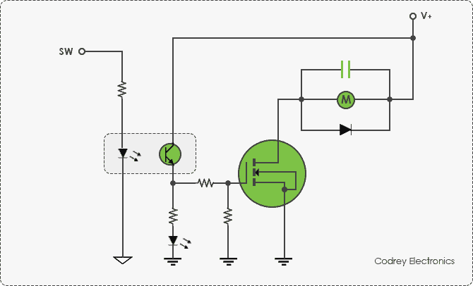
One snag of this concept is that although we’re using logic-level MOSFETs instead of ‘traditional’ ones meaning they switch at lower voltages but too suffer from slower switching time, gate capacitance, and on-resistance. All MOSFETs have a gate capacitor which is charged to start conducting and discharged to stop. This capacitor must be charged and discharged as fast as possible, otherwise, the MOSFET is in a semi-conducting state which dumps a lot of heat. Since they’re switched directly by the logic-level electronics, they might be switched slowly by the limited output the logic-level electronics can provide and this is further intensified by the issues pointed above. I have some suggestions on this but I get to that later.
More on coreless motor drivers
Making a very efficient coreless motor controller/driver is definitely outside the range of this article. However, here’re a few extremely useful exercises to go through.
For quick prototyping of a coreless motor system with two (or four) standard coreless dc motors, my advice is to use readymade multi-channel motor driver modules, even though it necessitates some extra stuff that’s to be added to complete the build. To explain the concept, I’d like to introduce a quite popular motor driver module – the Crowtail I2C Motor Driver.
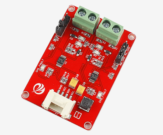
This pretty compact motor driver module can be used to drive any coreless dc motor as long as it doesn’t consume more than 1A at 5VDC. Two motors (1A x2) can be driven at the same instant while set to a different speed and direction. The speed can be set fully proportional and is controlled by I2C command. The I2C address of each channel is changeable!
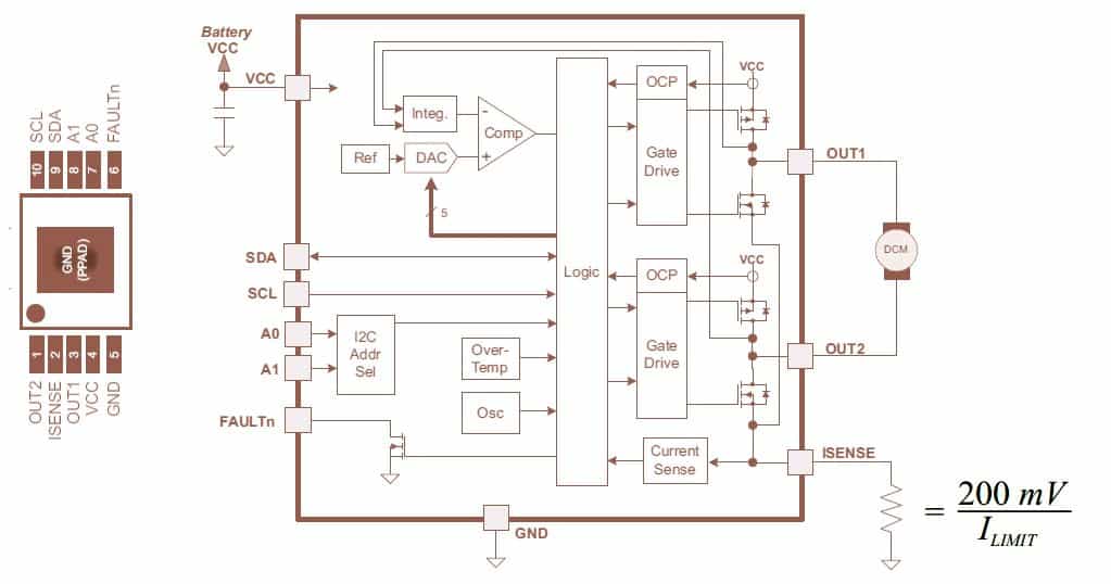
This I2C dc motor driver module is built around a pair of DRV8830 low-voltage motor driver from Texas Instruments (www.ti.com). The DRV8830 provides an integrated motor driver solution for battery-powered toys, printers, and other low-voltage or battery-powered motion control applications. The chip has one H-bridge driver with PWM voltage-control circuitry with current limit circuitry, and can drive one dc motor or one winding of a stepper motor, as well as other loads like solenoids. The output driver block consists of N-channel and P-channel power MOSFET’s configured as an H-bridge to drive the motor winding. Provided with sufficient PCB heatsinking, the DRV8830 can handle up to 1A of DC/RMS or peak output current, and it operates on power supply voltages from 2.75V to 6.8V. See its functional block diagram below.
Build your own coreless motor driver modules
You can ofcourse build your own coreless motor drivers using discrete parts. If so, keep note that the purpose of motor driver is to control the motor effectively. Often this requires that the voltage applied to the motor is modulated in some manner, for the purpose of speed control in particular. This is where a power-switching element (a MOSFET, for example) is used. The initial stage in selecting the correct power switching element for your motor drive application is understanding the motor being driven. Understanding the ratings of the motor is an important step in the process as it is often the corner points of operation that will determine the selection of the power switching element. For more valuable hints, it’s a good idea to have a look at this note http://ww1.microchip.com/downloads/en/appnotes/00898a.pdf
On a side note, the NTE series logic-level MOSFETs are compatible with the 5VDC power-supply requirement of logic circuitry. These MOSFETs do not require an interface circuit between it and the CMOS logic driver; therefore, the extra expense of the interface circuit power supply can be obviated. The selector guide https://www.nteinc.com/Web_pgs/LL_MOSFET.html
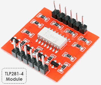
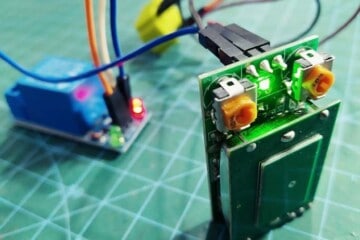
Simply, by using four logic-level MOSFETs and a four-channel optocoupler you can build your own four-channel isolated coreless motor driver module. I built such a module on a little perfboard a while ago but unfortunately, the saved images seem to have vanished from the storage while this was written. It’s input circuitry is based on a TLP281-4 optocoupler module (bought from robu.in) – sure proof!
PWM motor speed regulator & a bit of maths
PWM (Pulse Width Modulation) is an efficient way to govern the speed and power of electric dc motors. For better switching, however, the switching frequency should be much higher than the dynamics of the motor so that the motor should feel that it’s powered from a true dc voltage. According to trusty references, the switching frequency must be at least five times (x5) higher than the rotation speed of the motor. So, if the RPM of the motor is 12000 (200 rps), the switching frequency must be greater than 200x 5 = 1000Hz (1kHz).
Now to a bit serious ‘theoretic’ explanation. According to textbook electronics, it’d be better to set the switching frequency much higher than 1/(L/R) of the motor, where L/R is its electric time constant. Here L is the inductance and R the inner resistance of the motor. If L=1 mH and R=1Ω for a typical dc motor, then again the switching frequency must be higher than 1/(1mH x 1Ω) = 1000Hz (1kHz). In principle, a switching frequency around 20kHz is used usually to avoid noise from the motor in the audio range. Thanks to www.picotech.com
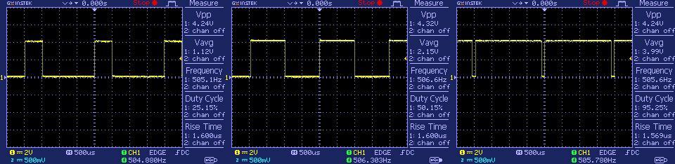
Below image depicts some oscilloscope views of the signals generated by a microcontroller based PWM motor speed regulator recently prepared by me. You can see pulse output at 500Hz and 25% – 50% – 95% duty cycle.
And, finally…
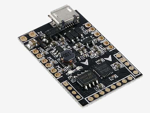
One thing I want to do next is to build a little drone with coreless dc motors for my personal use. While I’m looking for an all in one ready to go coreless motor driver, I chanced on a pretty promising module – the “CC3D Brushed Flight Controller” (see next image). If this makes sense, I think you too are good to go. If I’m diving too far into, I can give you more details about the project. Expecting the best…
Very useful info…
Arun patole: Thanks, this encourages me to put more of alike stuff. If you enjoyed this primer, you won’t want to miss my upcoming posts. So, please stay tuned!
I have to control a coreless motor by using a mosfet. It seems like above you mentioned a picture which is under “How to drive a coreless motor? “. Does that simple diagram work for you? If it works, please share with me the details of resistor value, capacitor value, transistor name, and so on. It will be more helpful for me.
Muhaimin: You may try the following parts (or equivalents):
MOSFET: IRL520 (Logic-Level Power MOSFET)
Diode: 1N4007
&
Gate Resistor 1 (between input and the gate): 100 Ohm 1/4W
Gate Resistor 2 (between gate and ground): 10K Ohm 1/4W
Capacitor: 100nF (0.1uF) Ceramic Capacitor
Let me know how this worked for you. Thanks!
Dear Mr Hareendran,
Very interesting to delve deeper into the coreless engine. We don’t think about it, but the drone topics and more will surprise you with the developments.
A question for you:
Since I am building a drone based on the Arduino Esp8266, controlled with a mosfet, is it possible to measure the rotational speed (RPM) and make it visible?
Thanks for an answer and greetings
Ger
Ger Smit: Thanks for your comment!
I regret, such an idea has not been tested yet, so I am helpless at this point.
But see, you can measure the RPM from BEMF as explained in this post (https://www.precisionmicrodrives.com/ab-021).