On COVID-19 lockdown days, I came across several motor driver modules in my scrap box in the attic – surprisingly most of them are unused Chinese modules. The L293 Arduino Motor Driver Shield, in particular, is extremely elegant, and I wanted to see how to play with that gem. Well, I figured it’s about time that I shared my own experiences with the L293 Arduino Motor Driver Shield. This is not intended to be an in-depth tutorial as there is plenty of information already out there. I’ve just presented briefly how it’s enough to inspire me!
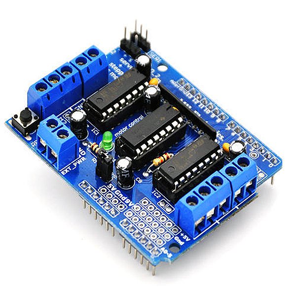
L293 motor driver shield
Quite often you’ll need a full-featured motor shield for your Arduino based mechatronics projects as such a compact shield can control a number of everyday dc motors, servo motors, and stepper motors. Besides such devoted dc motor shields will help you to drive certain solenoids and electromechanical actuators. Perfect for most mechatronics projects!
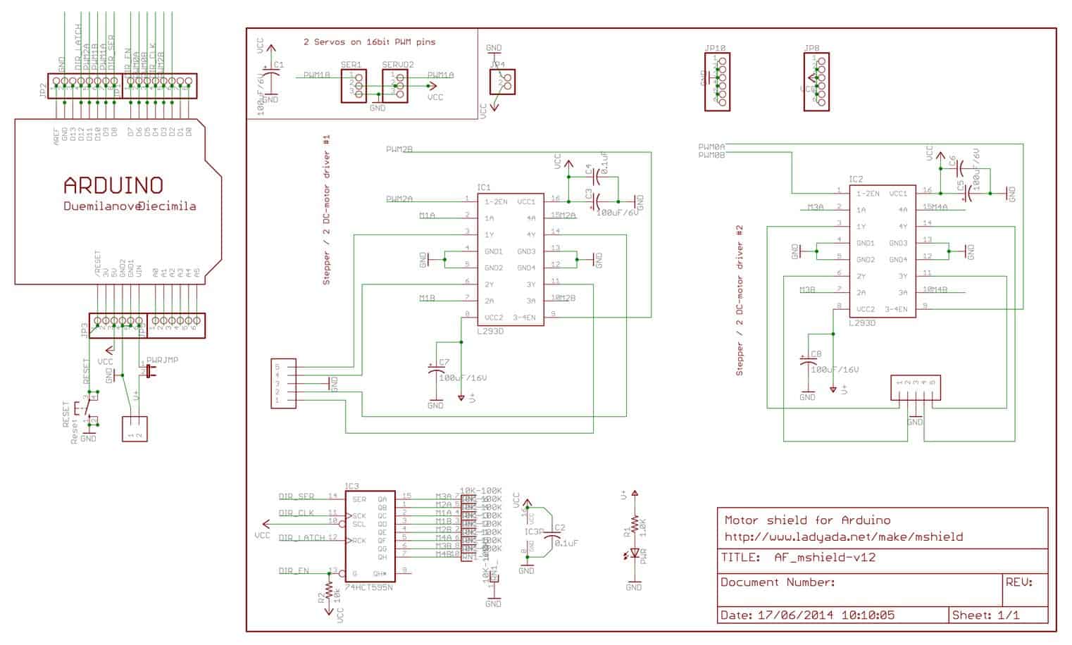
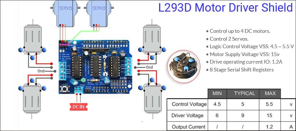
The motor driver shield comes with two L293D dual-channel H-Bridge motor ICs, so it can individually drive up to four dc motors. The shield offers a total of four H-Bridges and each H-bridge can deliver up to 600mA drive current to the dc motor. The next key component of the motor shield is the 74HC595 shift register IC that extends 4 digital pins of the Arduino to the 8 direction control pins of the L293D ICs. This is the official (Adafruit) schematic drawing of the motor shield.
Note that the output channels of both the L293D ICs are broken out to the edge of the motor shield with two 5-pin screw terminals (M1-M2-M3-M4)to connect four dc motors having voltages between 4.5V to 25V DC. You can also connect two bipolar stepper motors to output terminals – one to M1-M2 and other to M3-M4. In case of unipolar stepper motors, you can connect the center taps of both stepper motors to the Gnd terminal. Moreover, the motor shield puts out the 16-bit PWM output lines to a pair of 3-pin headers to which you can connect two standard servo motors.
On a side note, a serious drawback while working with motors is the large amounts of electrical noise they generate. The motor noise can interfere with the rest of the electronics and can even spoil delicate/sensitive components. Capacitors are usually the most basic but effective way to suppress motor noise, and as such here I urged you to use at least one 100nF ceramic capacitor across the motor terminals. For the neatest noise suppression, you can use three capacitors for one motor – one across the power supply terminals and one from each terminal to the motor case.
This topic is nothing new and there’re already quite a few good posts on the web on this. But I thought I would try to provide a short note on how to filter out the electrical noise from motors in electronic circuits.
First off, keep in mind that the electrical noise generated by a dc motor falls into two categories – electromagnetic interference and the electrical noise generated on the power rails. To suppress the level of electromagnetic interference, motors should be placed as far away from sensitive circuits as physically possible. Further, the metal enclosure (shell) of the motor must be properly grounded. The electromagnetic interference (RFI) can also be coupled into the circuit, but this type of interference (common-mode interference) can be minimized effectively via a simple low-pass filter.
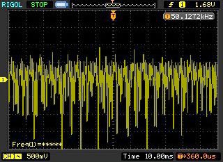
When it comes to the electrical noise on the power rails, filtering at the power source is needed. This can be done by including a ‘beefy’ capacitor across the power terminals. Following scope, capture denotes the noise at the battery terminal when a small toy car dc motor is powered directly by a 4.8V battery pack (Thanks to Kerry D. Wong). See, the noise level is quite severe and the noise Vpp level cut through 3V at times, which is high enough to cause malfunction especially in digital/logic circuits.
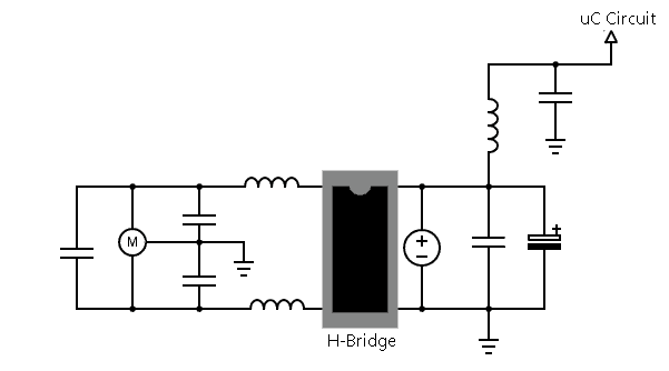
The example circuit shown next is tailored for filtering out dc motor electrical noise in bidirectional motor drivers. The values for the inductors (hundreds of mH) and capacitors (hundreds of nF) used in the schematic can be varied empirically to achieve optimum results. Needless to say, there’re several precautions you can take to help minimize the effects of motor electric noise on your system. Practice makes perfect!
To sum up, with adequate shielding, grounding, and correct filtering practices the electrical noise generated by a dc motor can be reduced to a level that is ‘invisible’ for even the most sensitive electronic circuits.
Play safe with your ideas
Getting back to the principal theme, a terminal block with a jumper is included in the motor shield to power the motors. Note that an Arduino can only give a few hundred mA on the 5V Arduino header. So, I strongly recommend to use an appropriate dc supply for the dc/stepper motors in use (the servo ports are internally powered and does not use an external power supply). That is to say, simply plug in the 9VDC supply for the Arduino board into its dc input jack, and connect the dc/stepper motor supply to the external power block (EXT_PWR) of the motor shield. Always ensure that the power supply selection jumper (PWR) is removed from the motor shield. Remember, the stepper and dc motor connections will not work if the onboard green indicator LED is not lit brightly!
Before using the L293D motor driver shield with Arduino IDE, you need to install the AFMotor library. This Adafruit library contains the requisite commands to control dc, stepper and servo motors. However, driving servos with the motor driver shield is pretty easy as the motor driver shield actually breaks out Arduino’s 16-bit PWM output pins 9 and 10 to the edge of the shield with two 3-pin ‘servo’ headers. Since you’re using the onboard PWM pins, the sketch works with the built-in Arduino Servo library. The aforesaid AFMotor library can be downloaded from here
https://github.com/adafruit/Adafruit-Motor-Shield-library
About my initial tryout
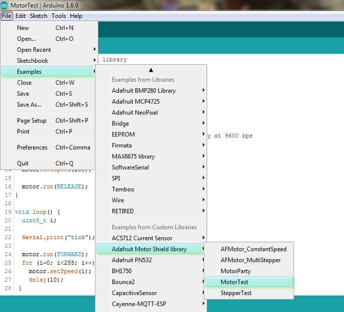
My first try was with the “MotorTest” example sketch included in the AFMotor library (see below). Obviously here you need to declare the motor port number to which the motor is wired. For port M1 write 1, for M2 write 2 and so on. Also if you want to connect multiple motors to the motor driver shield, you need to create a separate object for each motor.
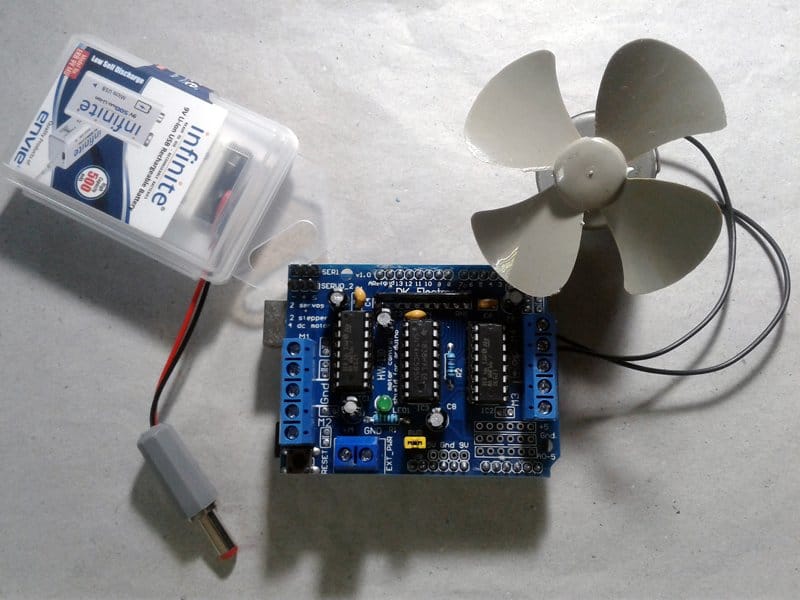
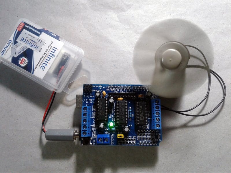
For the quick test, I used a small dc motor (5V/100mA) of a desktop USB fan, wired to M4 screw connector of the motor driver shield. One 6F22 9V rechargeable battery is used to power the entire setup – Arduino Uno + L293 motor driver shield – at that time, and it worked the right way (watch the quick test video).
And, see the casual lab snaps:
What’s next?
The proposed mechatronics hobby project centered on this L293 Arduino Motor Driver Shield (v1.0) is mostly ready, and I am now waiting for a few to supplementary parts to arrive in the next few weeks. I will document my build and post the final results in the near future. Good luck with developing your own ideas and creating your own systems. See you again soon!
The long list of credits & references includes: