Using an Attiny85 microcontroller is an attractive and economical way to build a minuscule Arduino project backed by a few lines of code. Very often such a project will demand an external adapter to program the Attiny microcontroller with the help of an Arduino board, and using a small ready-to-use module can reduce development time and gain flexibility. In this article we propose one idea and present our first module, designed for quick programming. More modules will be presented in the future.
Component List
- 16-Pin ZIF Socket or 8-Pin DIP IC Socket x1
- 7-Pin Relimate Connector x1
- 3mm Blue LED (Vf=1.9V-2.6V @ 20mA) x1
- 330R ¼ w Resistor x1
- 10uF/50V Electrolytic Capacitor x1
- 100nF Multilayer Ceramic Capacitor x1
- Attiny85-20PU Microcontroller (for your upcoming projects) x1
- Arduino Nano v3 Board (only for tiny programming) x1
Wiring Diagram
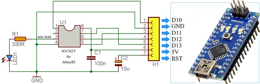
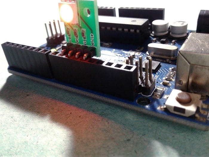
We have not yet made the printed circuit board for this design, but it is easy enough to use a small piece of prototyping board. For programming the Attiny85 we can use an Arduino Nano board and our little adapter. No special programming software is needed as we’ve the Arduino development environment (and its additional board manager’s help).
Tiny Programming…
At first, start your Arduino IDE (as usual) and keep the Arduino Nano board connected with the programming adapter (as pointed in the wiring diagram) within easy reach. Now configure the IDE by following the procedures given next:
- Navigate to File >> Preferences and add this URL to Additional boards manager URLs
- https://raw.githubusercontent.com/damellis/attiny/ide-1.6.x-boards-manager/package_damellis_attiny_index.json
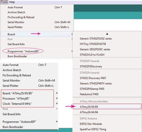
- Select your Attiny from the dropdown list of Boards
- In the Tools >> Clock menu, change the Clock to internal 8 MHZ
- Select Arduino ISP in the Tools >> Programmer menu (& Burn Bootloader)
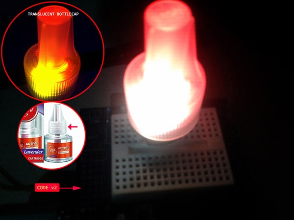
Finally upload this stripped test code and power cycle the setup after that. If everything is okay, you can see the blue LED starts blinking in your standalone Attiny85 circuit.
Finally upload this stripped test code and power cycle the setup after that. If everything is okay, you can see the blue LED starts blinking in your standalone Attiny85 circuit.
int ledPin =4; //Pin 3
//int ledpin =0; //Pin 5

void setup() {
    pinMode(ledPin, OUTPUT);
}

void loop() {
  digitalWrite(ledPin, HIGH);
  delay(500);
  digitalWrite(ledPin, LOW);
  delay(500);
  }
Note that you can connect the LED with pin 5 of Attiny85 after changing the line “int ledPin =4;” as “int ledPin =0;“.
Why the 10uF Capacitor? The auto reset circuit in Arduino Nano is a 100nF capacitor between RST on the microcontroller, and DTR on the usb-serial adapter. DTR is brought and held low when the serial port is open, and the 100nF capacitor turns this into a pulse on reset with the help of a 1K/10K pull-up resistor. This causes the bootloader to run, enables us to program the Arduino Nano over serial without a manual reset. Obviously, here we really don’t want it to reset when we open connection to serial port. The added 10uF capacitor hampers the ‘unwanted’ auto reset process!
Author’s Note: The idea presented here is for hobbyists adept in microcontroller projects, hence should be tried by the reader, at his or her own risk and responsibility. There may be concept, design and link errors in the article. I correct and update errors or links as I find them!