This time I’d like to share my funny thoughts on the build of a very ‘hobbyist’ digital toggle switch device. The project idea keeps things as simple as they can be. You have a sensor slot and an electronic switch. When a debit/credit card (or any other opaque card) is inserted into the sensor slot, the electronic switch comes on, and when the card is inserted for the second time, it goes off. The design configuration is very adaptive and you could create a tricky electronic door lock without costly parts by using a standard door lock solenoid. How is that?
The Tiny Hardware
One of the first boards many Arduino hobbyists prefer as an alternative to do little projects is the Digispark Attiny85 development board, and you can find a good primer elsewhere here. In this post, I hope to help newcomers take their next ‘tiny’ step!
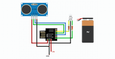
The following figure depicts the complete hardware diagram of the project. As you can see, apart from the Digispark board, only one extra component is used here – the H21A1 phototransistor optical interrupter switch from Fairchild Semiconductor. The entire hardware is prepared to run on a 5V power bank/USB power supply. In the circuit, the sensor output is wired to P0 of Digispark while P1 of Digispark is configured to give a logic-level signal output to control the external load through an appropriate driver circuitry. The green LED in the setup wired to the same P1 is a crude ‘debug’ indicator, in fact, a pointless inclusion left to personal choice.
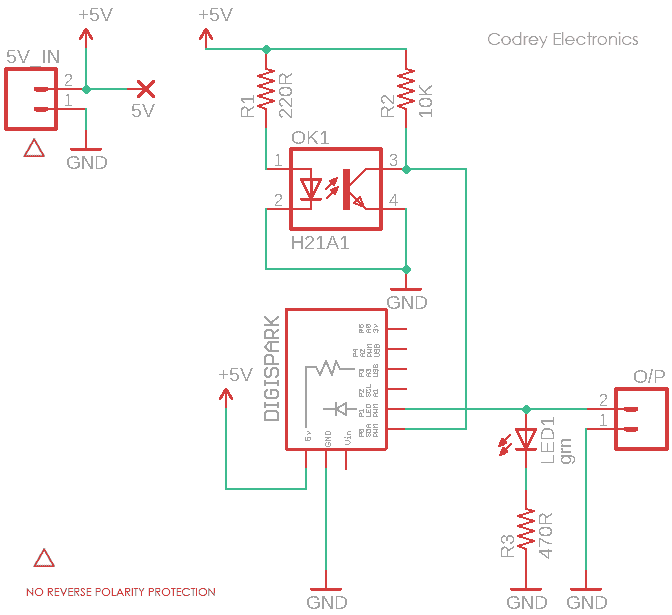
Digispark’s VIN pin happily accepts 7-12VDC (9V typical ) input and its onboard fixed-voltage linear regulator chip (78M05) can cater current up to 500mA at 5VDC via the 5V header pin. Therefore, when you run this circuit from a 9V battery, then you can take regulated 5VDC output through the 5V header pin. There’s a bit of subtlety here: current draw over 100mA might need some heatsinking!
The same 5V header pin can be used to energize the Digispark board as well. That means if you don’t want to use a 9V battery in your setup (like me), then you can feed regulated 5VDC to the circuit available from any usb power source (a power bank, for example) through the 5V header pin. Also note that GPIO output of Digispark is 20mA maximum per pin same as a regular Arduino.
The Digispark Sketch
This sketch will do the task exactly as pointed before. Swipe the card to turn on the output, and swipe it again to turn off the output. The code given below is not an original one as I used it in a recent project, and in fact it’s an adapted piece of code originally formulated by Martyn Currey (www.martyncurrey.com).
/*
 * Funny Digital Toggle Switch
 * Hardware: Digispark Board & H21A1 Sensor
 * Sketch: Adapted Version (See Acknowledgement)
 * Author: T.K.Hareendran/2020
 * Publisher: codrey.com
 */

int pin_OUT = 1; //Drive Output Pin = P1
int pin_SEN = 0; //Sesnor Input Pin = P0
boolean oldSenState = LOW;
boolean newSenState1 = LOW;
boolean newSenState2 = LOW;
boolean newSenState3 = LOW;

boolean OutState = LOW;


void setup()
{
    pinMode(pin_OUT, OUTPUT);
    digitalWrite(pin_OUT,LOW);

    pinMode(pin_SEN, INPUT);

}

void loop()
{
    newSenState1 = digitalRead(pin_SEN);
    delay(1);
    newSenState2 = digitalRead(pin_SEN);
    delay(1);
    newSenState3 = digitalRead(pin_SEN);


    if (  (newSenState1==newSenState2) && (newSenState1==newSenState3) )
    {

        if ( newSenState1 != oldSenState )
        {


           if ( newSenState1 == HIGH )
           {
               if ( OutState == LOW ) { digitalWrite(pin_OUT, HIGH);  OutState = HIGH; }
               else                    { digitalWrite(pin_OUT, LOW);   OutState = LOW;  }
           }
           oldSenState = newSenState1;
        }
    }
}
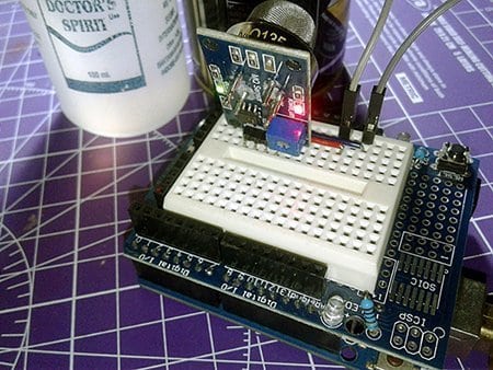
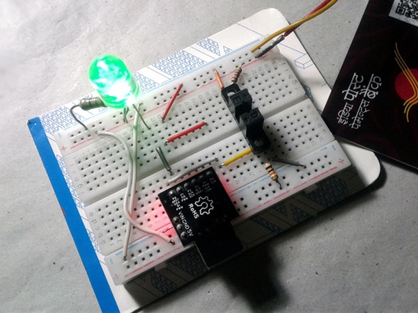
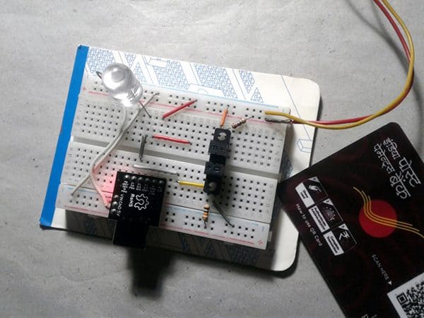
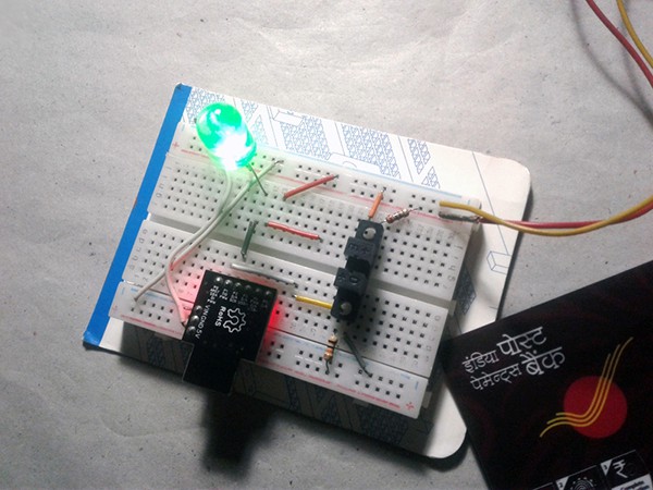
Following is a pair of snapshots from my workbench:
The Power Driver
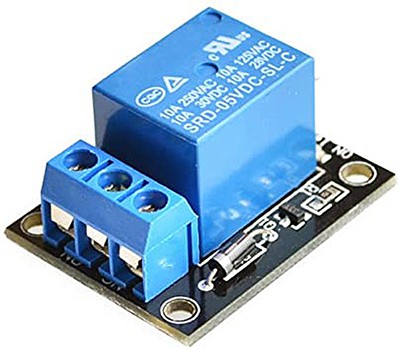
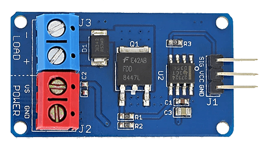
There is a small problem however, the Digispark will only put out 20mA (@5V) from the P1 pin which is insufficient to drive an external load like an electromechanical relay. This obviously calls for a devoted power driver circuitry. You can simply wire an n-p-n transistor as a low-side switch to carry out that, and the cheapo S8050 transistor (ofcourse with one 1KΩ base resistor) will be a good candidate. Not to mention it’s quite capable for the task, and perhaps you may have plenty of them at your lab. Lazy guys may go for a prewired 5V relay module (see below), ha ha, but that’s not a bad practice in these days!
Now that that’s out of the way, let’s talk about another driver idea based on a common power MOSFET. Since my real intention was to build a card-operated simple door lock with a cheap door lock solenoid, I did a thorough Google search and came across an ultra-compact power MOSFET module originated in China (see next figure). The little driver module holds a 50A power MOSFET (FDD8447L) and a dedicated MOSFET gate driver chip (UCC27324-Q1).
Frankly, a logic-level MOSFET, like the IRL540, can work together with the given toggle switch circuitry to handle a standard door lock solenoid or a small linear actuator efficaciously, and in that sense, I made a costly mistake. But I’ve a good reason for that (more on later)!
One side note: The I/O pin of a microcontroller is usually adequate to drive a small-signal logic-level MOSFET, and in principle digital signals are meant to drive small loads on the order of 10-100pF (larger MOSFETs have higher gate capacitance which can be in the thousands of pF). A MOSFET driver IC translates logic level signals into a higher voltage and higher current to quickly and entirely switching the gate of a MOSFET. Also, common MOSFETs have a higher gate voltage, so a logic-level signal is often not decent for the MOSFET. Moreover, a switching MOSFET might cause a back-current from its gate back to the driving circuit which is a serious issue in most situations. A MOSFET gate driver IC is designed to manage this back current, too. If you want to see more relevant information about MOSFET gate driver circuit guidelines, then go through this Kynix ™ link www.kynixsemiconductor.com/News/47.html
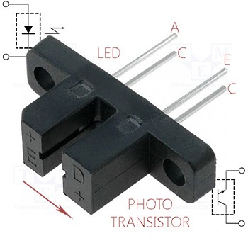
Back to the project, this is the pinout of the H21A1 slotted optical sensor. The H21A1 consists of a gallium arsenide infrared emitting diode (emitter) coupled with a silicon phototransistor (sensor) in a plastic housing. The maximum forward voltage (VF) of its emitter component (infrared emitting diode) is 1.7V at 60mA continuous forward current (IF). Similarly, the absolute maximum collector to emitter voltage (VCEO) of its sensor component (phototransistor) is 30V, and the collector current (IC) is 20mA. In my prototype, VF is around 1.2V at near 18mA IF.
A note on construction
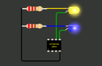
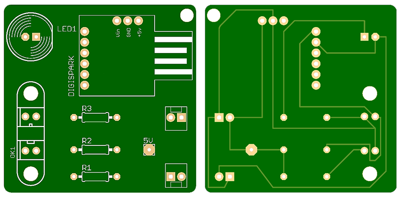
The remarkably simple project can be built on a small perforated circuit board as there’s no SMDs. With a little imagination and thought it’s aboveboard enough to put the components together. Of course, there’s nothing to deter you from creating your own PCB. Below you can see the initial artwork of a single-sided demo PCB cooked by me – simply to give an impression of the final build (with a little bit of retouching, it is possible to obtain more pleasing layouts). If highly demanded, an exclusive link for downloading the final Gerber files will be posted here in the comments box after a couple of weeks.
Finally, to avoid any misunderstanding, I should point out that this is just a funny do it yourself electronics project. To keep the design within the range of an average hobbyist, I opted for a simple and adaptable approach with minimal components. That’s all for now!