As Maya Angelo, an American civil rights activist and poet, once said, Do the best you can until you know better. Then when you know better, do better! So, here’s a review post to keep you updated – Arduino Analog and PWM Secrets!
Arduino Analog
Analog Input
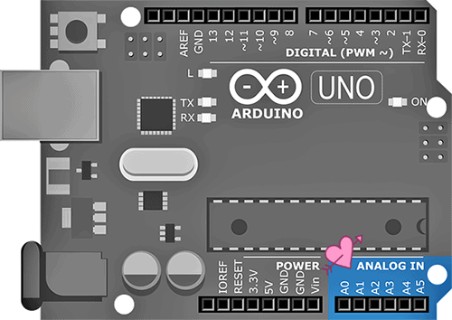
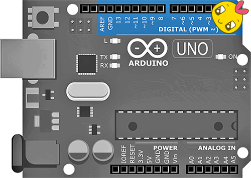
An Arduino has a number of analog inputs, which enables us to measure analog parameters like a voltage, current, resistance, temperature, light and so on. As you already might have noticed, the Arduino Uno has six analog input (ANALOG IN) pins. Usually, the selection of the analog input is done by “analogPin = n;” where n is the analog pin number.
The basic usage is very simple → int value = analogRead (A0); // Read A0
This results in a number in the range 0-1023. Using default settings, a return value of 0 would represent approximately 0V, and a return value of 1023 would represent approximately 5V.
Number to Voltage
When it comes to converting a measurement from a number to a voltage, we need to multiply the reading by the size of step.
So, for a reading of 512: V= 512 x 5.000/1024 = 2.5 Volts.
John Errington’s page has lots more very useful information https://skillbank.co.uk/arduino/adc.htm#adc2.
Analog Reference
To measure an analog signal there has to be a voltage level to compare it with. This voltage is called the reference. In the ATMEGA328 at the core of the Arduino Uno, this reference voltage is also the maximum voltage that can be measured.
The Arduino has three reference voltage options: AVcc (default reference voltage) which is connected to the digital 5V rail, the internal 1.1V and the option to use an external voltage reference. The voltages are always measured relative to the ground (GND). The analog reference voltage can be set with the function “analogReference()“.
Now note that since the measurements of the input voltages are made relative to the reference voltage, fluctuations of the reference voltage will influence the result!
External AREF
The default reference voltage AVcc is only useful when measuring voltages that are directly dependent on the supply voltage. But the internal 1.1V reference is more stable and hardly depends on the supply voltage or temperature (thus absolute measurements can be made). Simply, it’s good for exact measurements of external voltages.
Summed up briefly, we can choose three different analog reference voltages:
- AVCC: analogReference (DEFAULT);
- Internal 1.1V reference: analogReference (INTERNAL);
- External provided at AREF pin: analogReference (EXTERNAL);
The external voltage reference option (AREF) can be used to feed a known, steady, and clean voltage reference. The Atmel datasheet states that the external reference voltage must be in the range 1V to VCC. That means, since Arduino Uno has a Vcc of 5V, the AREF must not exceed 5V.
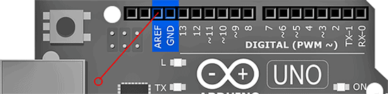
At this point, note that once you do an analogRead if you use either of the internal voltage references (default 5V or internal 1.1V) it’s connected to the AREF pin internally. So, you should not connect any other voltage sources to the AREF pin or it will be shorted to the internal reference. Look, if you’re applying an external reference voltage to the AREF pin without this protection , you must set the analog reference to EXTERNAL before the analogRead call.
Also, Atmel recommends putting a capacitor between AREF and GND to smooth out the voltage on that pin, and probably a 100nF would do the job!
Moreover, for best results it’s advised to choose a reference that is just a little higher than the expected range of your unsure input. So, if you expect a maximum of 2V, a 2.5V reference would be a clever choice. However, if you’re measuring from a potentiometric sensor then the default reference is often ideal.
Warning: Don’t apply anything lower than 0V or higher than 5V for external reference voltage on the AREF pin!
Arduino PWM
PWM (pulse width modulation) is a technique for getting an analog result through a digital way. That is, digital control is used to create a square wave switched between on and off, and the on-off pattern can simulate voltages in between the full Vcc of the board (5V on Uno) and off (0V) by changing the portion of the time the signal spends on versus the time that the signal spends off. The duration of “on time” is called the pulse width. To get varying analog values, you can change (or modulate) the pulse width.
A call to analogWrite() is on a scale of 0-255, such that analogWrite(255) requests a 100% duty cycle (always on). The PWM signal is repeated at a constant frequency i.e., the start of each PWM signal is separated from the next start pulse by the same period.
Uno PWM
For the standard Arduino Uno there’re six analog output pins you can use. Note that there’re two main PWM frequencies used in Arduino boards – 490Hz and 980Hz. The reason for the different frequencies is that Timer 0 is shared with functions delay() and millis(). These are on pins 5 and 6 on the Arduino Uno.
Arduino Uno PWM pins are 3, 5, 6, 9, 10 and 11. Recall, the analog output pins 5 and 6 use 980Hz and the analog output pins 3, 9, 10 and 11 use 490Hz.
The function to set any of the PWM pins to a specific mark to space ratio is analogWrite(pin, msvalue);
The argument pin is any of the valid PWM pins. The argument msvalue (mark:space ratio)can take a value from 0 to 255.
8-bit PWM
The resolution of the Uno PWM signal is 8 bit. Therefore, there’re 256 distinct output values of mark to space ratio, and when averaged results in 256 different voltage levels. The PWM value 0 results in zero output, and the PWM value 255 results in a fully-on output.
There’re three Timers in the Arduino Uno chip (ATmega328P) and in general each timer is capable of handling two PWM outputs. Actually, Timer 1 is capable of being used as a 16-bit PWM but is limited in software to an 8-bit output to maintain consistency with other PWM outputs.
Analog Output
Arduino Uno’s analog output pins do not create a true analog output as the microcontroller does not have a resistive diver to generate the voltage. Instead, it uses a digital PWM signal that can be smoothed to create an average voltage, which does result in a final analog output. The key difference between a true analog output voltage and a PWM voltage is that the latter is created using varying the mark to space ratio within the digital output signal. In short, varying the mark to space ratio alters the average voltage at the output which can be smoothed into a steady dc voltage to create the Arduino analog output. It’s a pretty simple trick for generating an analog output voltage using only digital signals!
FAST 8/10-bit PWM DAC
Since Arduino has no integrated DAC (digital to analog converter) we’ve to use the standard Arduino function analogWrite() to create the so called PWM DAC which’s in fact a PWM signal which has to be filtered with a low pass filter (LPF). However, this method has a drawback as the regular analogWrite() function is very slow!
But it’s now possible to create fast 8/10-bit PWM signals using an Arduino Uno!
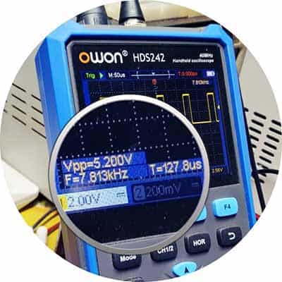
(The PWM frequency is then 31250Hz for 8-bit instead of the standard 490Hz, and the resolution can be set to 8-bit or 10-bit. For 8-bit the PWM period is 32us/31.25kHz while for 10-bit the PWM period is 130us/7.8kHz).
I will explain this further through a unique practical project included in another post. Stay tuned! For the moment, you can go through this post https://www.avdweb.nl/arduino/adc-dac/fast-pwm-dac