This post shows how to get started with a quite popular and comparatively cheap color TFT display module with an Arduino Uno.
To start this experiment, you need the following key components.
- Arduino Uno R3
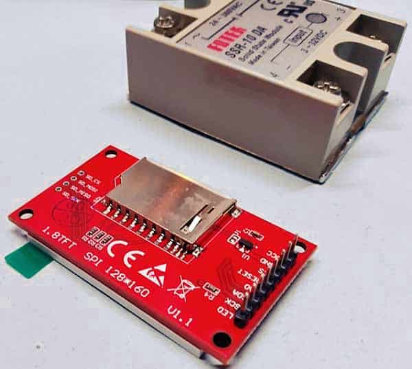
- ST7735 1.8″ Color TFT Display Module v1.1
- Prototyping Shield with Breadboard for Arduino Uno R3 (optional)
The ST7735 color TFT display is a 1.8″ display with a resolution of 128×160 pixels and can display an extensive range of colors. It utilizes the SPI protocol for communication, features its own pixel-addressable frame buffer, and only needs four I/O pins of a microcontroller. To complement the display, it also comes with an SD card slot on which colored bitmaps can be loaded and easily displayed on the screen.
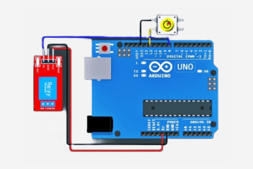
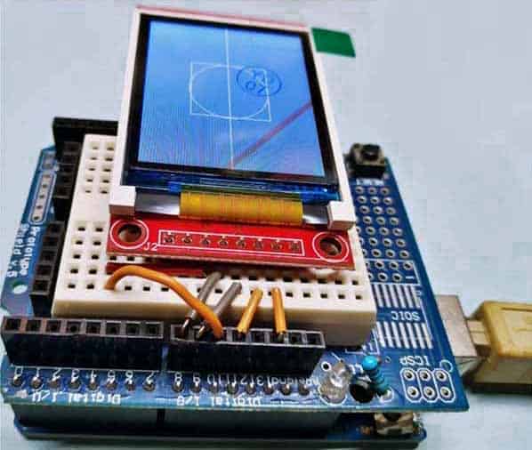
The hardware setup for this experiment is fairly easy as the only thing you need to wire with the Arduino Uno is the TFT display. Well, connect the TFT display module to the Arduino Uno as pointed in the table below.
| 1.8″ TFT Display v1.1 | Arduino Uno R3 |
|---|---|
| LED | 3.3V |
| SCK | D13 |
| SDA | D11 |
| A0 | D9 |
| RESET | D8 |
| CS | D10 |
| GND | GND |
| VCC | 5V |
The ST7735 is a single-chip controller/driver for 262K-color, graphic type TFT-LCD, which consists of 396 source line and 162 gate line driving circuits. This chip is capable of connecting directly to an external microprocessor and accepts Serial Peripheral Interface (SPI), 8-bit/9-bit/16-bit/18-bit parallel interface. Display data can be stored in the on-chip display data RAM of 132 x 162 x 18 bits.
The ST7735 can perform display data RAM read/write operation with no external operation clock to minimize power consumption. In addition, because of the integrated power supply circuits necessary to drive liquid crystal, it is possible to make a display system with fewer components
ST7735 Datasheet https://www.displayfuture.com/Display/datasheet/controller/ST7735.pdf
Also read this loosely related guide http://www.lcdwiki.com/1.8inch_Arduino_SPI_Module_ST7735S_SKU:MAR1801 Now, you can see below a seller’s description of the TFT display used in my experiments.
Now, you can see below a seller’s description of the TFT display used in my experiments.
| Driver IC | ST7735 |
| Display Size (inch) | 1.8 |
| Input Voltage (V) | 3.3 to 5 |
| Pixel Resolution | 128 x 160 |
| PCB Size (L x W) mm | 58 x 35 |
| Interface Type | SPI |
It’s very crucial to note at this point that the maximum power supply voltage for the ST7735 display driver chip is 3.3V and same for its interface pins. Some TFT modules include a 3.3V regulator and a logic level shifter onboard in which case it can be used with any 5V microcontrollers. If not, some logic level shifting must be done if the microcontroller is not powered from 3.3V!
Now to an example/test code.
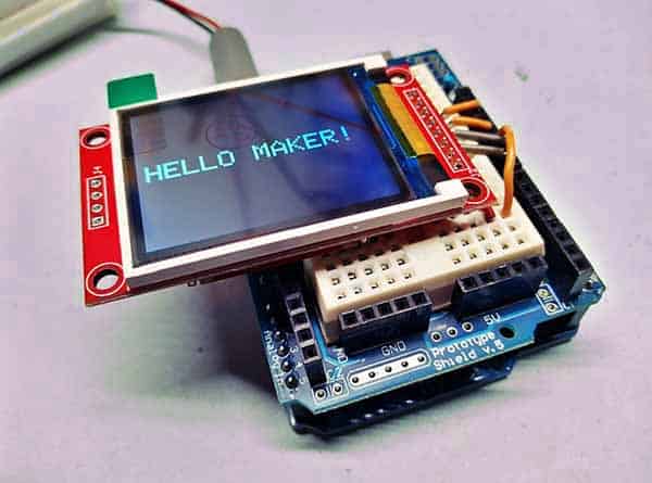
Copy the following code to your Arduino IDE and upload it to your Arduino Uno. This code displays “HELLO MAKER!” in the middle of the screen and changes the font color every 500 milliseconds.
#include <TFT.h>
#include <SPI.h>
#define cs   10
#define dc   9
#define rst  8

TFT TFTscreen = TFT(cs, dc, rst);

void setup() {
  TFTscreen.begin();
  TFTscreen.background(0, 0, 0);
  TFTscreen.setTextSize(2);
}

void loop() {
  int redRandom = random(0, 255);
  int greenRandom = random (0, 255);
  int blueRandom = random (0, 255);

  TFTscreen.stroke(redRandom, greenRandom, blueRandom);
  TFTscreen.text("HELLO MAKER!", 6, 57);
  delay(500);
}
Note that since the TFT display communicates with the Arduino via SPI communication, you need to include the SPI library in your code. You also need to use the TFT library, which’s already included with Arduino IDE 1.0.5, and later, to write and draw on the TFT display.
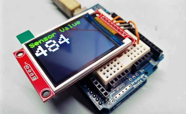
Below is another easiest example code to manifest the possibilities of the TFT display. This no-frills Arduino Sketch simply displays the value of Uno’s analog input A0 on the TFT display.
#include <TFT.h>
#include <SPI.h>

#define cs   10
#define dc   9
#define rst  8

TFT TFTscreen = TFT(cs, dc, rst);

char sensorPrintout[4];

void setup() {
  TFTscreen.begin();
  TFTscreen.background(0, 0, 0);
  TFTscreen.stroke(0, 255, 0);
  TFTscreen.setTextSize(2);
  TFTscreen.text("Sensor Value :\n ", 0, 0);
  TFTscreen.setTextSize(5);
}

void loop() {
  String sensorVal = String(analogRead(A0));
  sensorVal.toCharArray(sensorPrintout, 4);

  TFTscreen.stroke(255, 255, 255);
  TFTscreen.text(sensorPrintout, 0, 20);
  delay(250);
  TFTscreen.stroke(0, 0, 0);
  TFTscreen.text(sensorPrintout, 0, 20);
}
And sure enough, the TFT library enables the Arduino to communicate with the TFT display module, and it simplifies the process of drawing lines, shapes, images, and text to the display screen. Note that the TFT library relies on the SPI library for communication with the display and SD card, and needs to be included in all sketches. For additional information, see this page https://www.arduino.cc/reference/en/libraries/tft/.
That’s it for this quick primer guys, now you can easily add a nice visual interface to your projects using a cute TFT display.
In my book, this ST7735 display controller based 1.8″ colour TFT display is a very handy module for use in microcontroller projects. Here I just discussed about displaying elements on the TFT display but you can follow my upcoming tutorials to learn more about making a bit more advanced display projects.