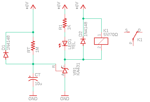
The real inspiration for this post actually came from lots of lame designs seen on the web. The last drop was a reasonably great written article presenting a number of blueprints to build timer circuits without using any dedicated timer chips. After a bit of thinking and couple of minutes bread-boarding, finally I came up with the following solution. It utilizes the three-terminal programmable shunt regulator diode KA431 (TL431) that form a pretty simple time delay switch.
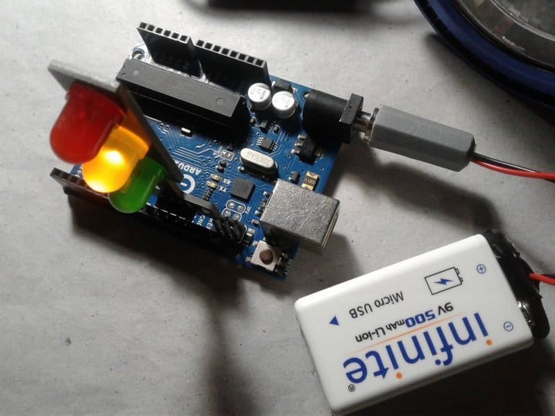
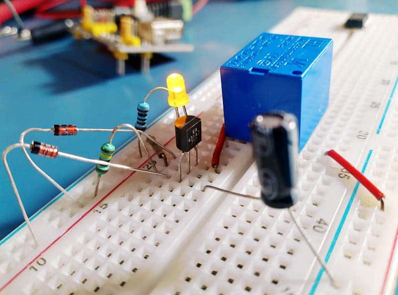
As drawn this time delay switch schematic works nicely. That is, the lamp wakes up roughly four seconds after it is powered up, also the relay merrily energizes as anticipated. Hooray!
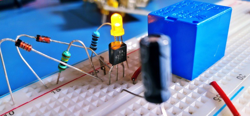
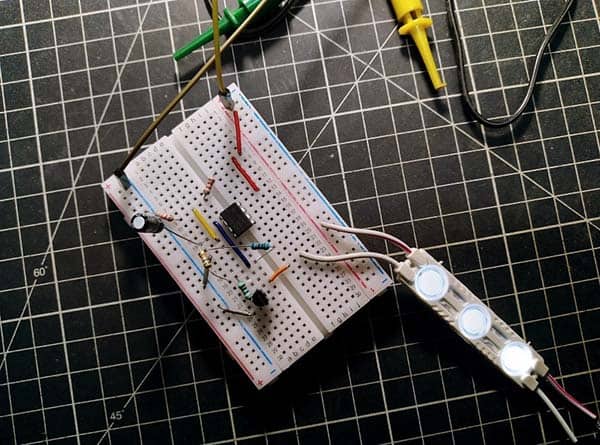
The TO-92 package of KA431AZ programmable shunt regulator is used in my breadboard prototype which has 1% output voltage tolerance. And it features 100mA maximum sink current capability.
In theory, KA431 without feedback can be considered as an NPN/NMOS device with high transconductance and precise 2.5V turn-on voltage. Now it is worth mentioning that KA431 will not let the voltage on its REF pin go much higher than its 2.5V threshold.
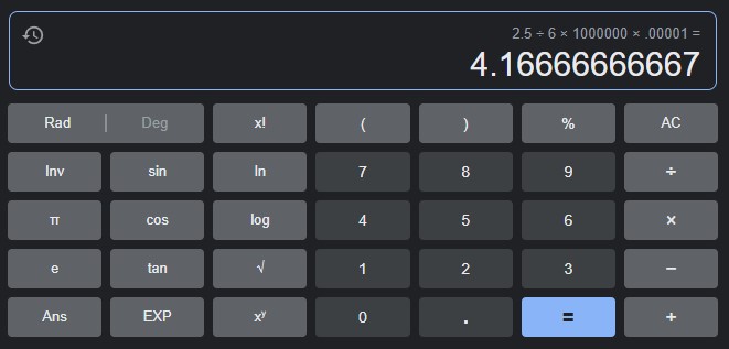
Note that in our basic timer configuration, the turn-on delay will be 2.5V/Vcc x (RT x СТ). So it is 2.5/6 x (1MΩ x 10uF) = 4.16 sec (see below).
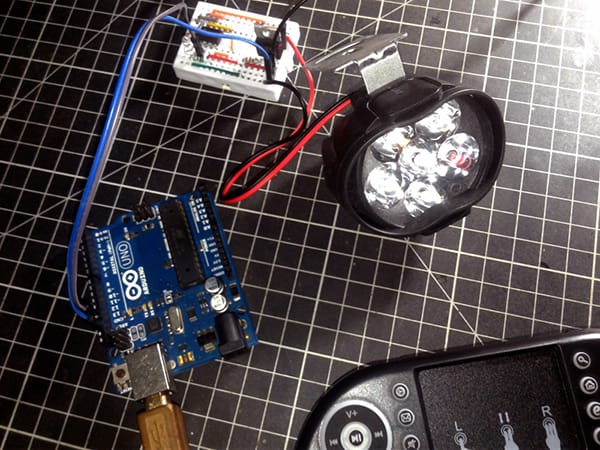
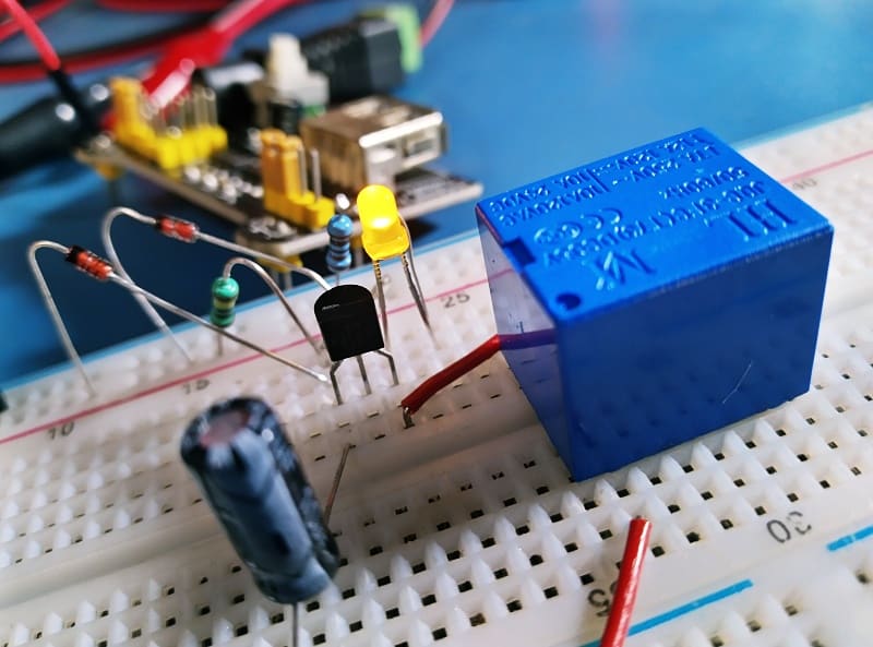
Another significant thing to notice at this point is that here we are driving a fairly low-current (70mA or so) relay (K1) directly with the KA431 (VR1).
Actually this is a despicable design practice because KA431 is able to pull its cathode terminal lower than 2.5V if the control input is higher, but that is an undocumented feature, and hence unstable and unpredictable.
In my case, the dropout observed is around 2V, and a “JQC-3F(T73)” series 5V relay works smoothly as its pick-up voltage is about 3.75V (≤75% of coil voltage). This may work for a one-off, but that is not the right way to design a circuit. So, I have to admit, my design concept needs to be refined, clearly ⚠
So perhaps the next feasible approach here is to use a jellybean PNP transistor to drive the relay, you can still hunt for better options though. This is left as an exercise to you!
Well, now you have a bit odd turn-on delay timer circuit that hardly employs any special timer ICs. The basic idea of the scheme presented here is a resistor-capacitor (R-C) timing network, linked to a precision programmable shunt regulator IC. Note that by modifying the values of the R-C timing components, the time period can be varied. The RT-CT values pointed in the schematic are merely an example for a functional circuit.
In conclusion, I am reasonably happy how this turned out. Obviously, there are some design flaws and in the next iteration I would do some things differently.