Do you know? You can govern the speed of brushed DC motors without any additional sensors, but using a basic characteristic – the speed-dependent back EMF (BEMF) voltage!
The BEMF motion control technique has been employed for decades mainly in audio tape transport mechanisms (see below).
Note at this point that measuring the voltage (electromotive force) generated by a spinning motor in order to determine its rotational speed is commonly called BEMF since the voltage tends to beat back against the circuit driving current into the windings of the motor. Since this voltage is directly proportional to the rotational velocity (and the physical properties) of the motor, its rotational velocity can be computed with no optical encoders, magnetic encoders, or other forms of an active feedback mechanism.
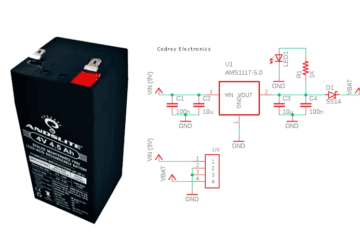
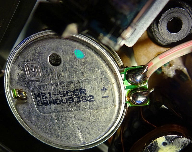
This is the partial inside view of a common tape deck motor. The integrated circular PCB has a dedicated motor speed regulator IC to monitor and control the motor speed, and an externally accessible trimpot is also there to fine-tune the speed when required (you can stick a small screwdriver through the hole in the top of the motor to turn the trimpot).
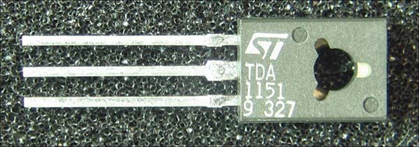
TDA1151 is a popular 3-Pin motor speed regulator IC that has been widely used in such applications. The TDA1151 is a monolithic integrated circuit intended for use as speed regulator for DC motors of record players, toys, record players, tape and cassette recorders.
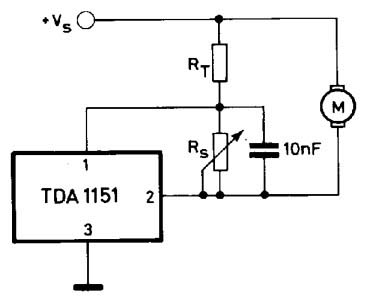
Below you can see its typical application circuit (borrowed from datasheet). Note that the 10nF ceramic capacitor wired between pins 1 and 2 improves stability in some applications.
Other common ICs that were previously popular in tape recorders included the LA5586, TDA7274, BA6220, AN6651, and AN6550. Sadly, most of these wonderful chips have been discontinued and are now only available from aftermarket sources!
Fortunately we can still use discrete transistors and op-amps to make sensorless analog motor speed controller circuits. This is an interesting technique as it operated linearly and did not generate any noise, like pulse width modulation based speed controllers.
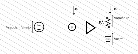
The first thing to note about at this point is that a DC motor can be modelled as a serial connection of internal resistance and BEMF voltage source. The voltage on motor terminals then is the sum of BEMF and the voltage dropped over the coil resistance (winding resistance).
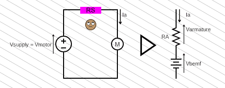
See, we can connect an external resistor in series with the motor to measure the voltage drop on that series resistor as this enables us to define the BEMF (if we set the value of the series resistor to be equal to the coil resistance in the motor, we ensure any change in the voltage drop across the series resistor is equal to the voltage drop in the armature).
Right now, as I am writing, I have just got one thought – by measuring the stall current of a brushed dc motor with a known supply voltage, we can loosely calculate its coil resistance (armature resistance). For example, when supplying the motor with 1.5VDC and measuring 200mA during stall, the armature resistance will be around 7.5Ω (1.5V/200mA = 7.5Ω).
Well, let us recap the key points…
- Any rotating coil will have an induced emf. In motors, this self-generated emf is called back emf (BEMF) because it opposes the emf input to the motor. A running motor generates back emf as it consists of a coil turning in a magnetic field.
- Since back emf is the generator output of a motor, it is proportional to the motor’s angular velocity ω. It is zero when the motor is first turned on, that means the coil gets the full driving voltage and the motor draws maximum current when it is powered up but not revolving. As the motor turns faster and faster, the back emf builds up, always opposing the driving emf, and scales down the voltage across the coil and the amount of current it draws.
- By adding an additional series resistor before the motor and reading the voltage drop across the series resistor, it is possible to measure the motor current. Thereafter, if we know the internal resistance (coil resistance) of the motor, it will be possible to calculate the BEMF of the motor circuitously.
- Resistance measurement of the motor’s armature (coil resistance) can be done by measuring the resistance across the motor’s terminals using a precise ohmmeter, or by measuring the stall current with a known power source.
Alright folks, this marks the end of this chapter! Next up, we have to build a practical circuit based on this concept. I will explain about a couple of design ideas in upcoming posts so do not worry if you do not empathize it yet at this point. If you have any questions, feel free to write it down in the comments section and I will get back to you as soon as possible 😎
Thanks to https://www.monolithicpower.com, https://www.precisionmicrodrives.com, https://www.audioappraisal.com, https://syntherjack.net/