This 5V microcontroller power rail guard is a quite simple solution to add an overvoltage protection (OVP) mechanism between the 5VDC power source and your microcontroller board.
In short, this little design uses a Zener diode and a BJT to monitor the 5VDC rail of the power supply and another BJT to drive an electromagnetic relay. When the input voltage rises beyond a certain threshold the relay cuts off the 5VDC output. So, the system can be run again after an over voltage incident but without taking the pain of replacing a glass fuse or the like. The schematic is shown below.
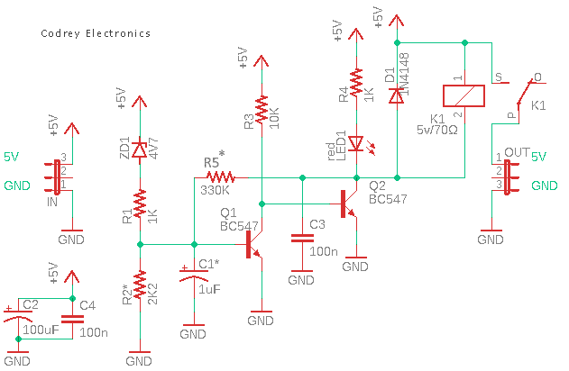
As you can see in the above schematic, the idea behind this design is very straight forward.
The key component of the overvoltage detection mechanism is a regular 4.7V Zener diode (ZD1). An SPDT relay (K1) with a 5V/70Ω coil is connected so that the +5VDC rail of the power supply has to go through its normally open (NO) contacts. Thus, when the relay is deactivated, the switching contacts open and power is removed from the positive output rail. Note that the system will auto-recover as soon as the power rail voltage drops below the threshold, also it has a red LED to indicate the normal voltage condition (relay in on state).
Because of fairly broad component tolerances and to reconcile the normal voltage variations of even regulated power supplies, the final build must be trimmed so the output voltage cuts off at circa 5.4VDC. A multiturn trimpot in lieu of the fixed 2.2KΩ resistor (R2) will help you to calibrate the exact over voltage threshold. Also, in certain cases it might become essential to alter the value of the 330KΩ resistor (R5) during circuit optimization. Keep in mind, Zener diodes are somewhat temperature sensitive components!
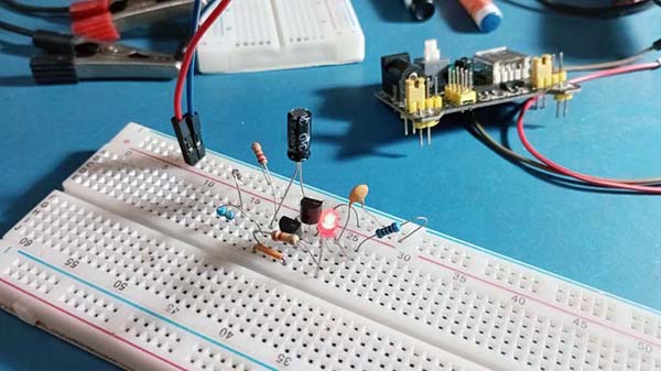
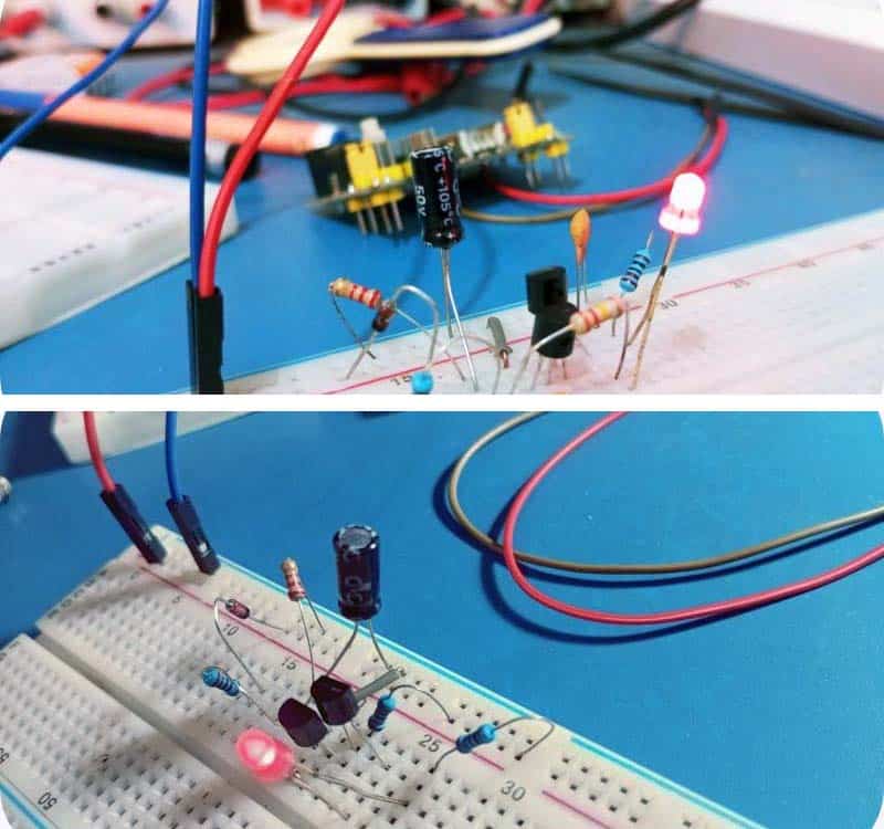
Below you will see a partial view of my breadboard prototype (just a random snap taken before adding the relay).
A more simplified version of the above concept follows. Here, the circuit provides a TTL logic-level signal depending on the value of the input rail voltage, i.e., a low signal (L) when there is a normal voltage input and a high signal (H) for an overvoltage condition.
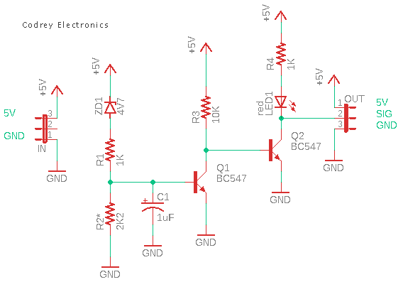
The signal output (SIG) of this circuit can be wired to a 5V microcontroller’s GPIO to detect the High/Low logic signals, provided it has a suitable pull-up resistor (10KΩ for instance).
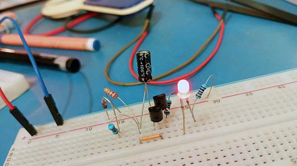
This is my quick breadboard setup:
So, this post presents two simple and easy to build power rail guard circuits for you to try. Finally, just to be clear, these solutions are for a 5VDC power supply rail but the same setup can be used with higher voltage DC power rails after a few modifications. Well, improve it with your clever ideas!
If you have an LED on to signify proper operation, consider using a GREEN one.
Red is associated with danger, so red LED’S should be reserved for “fault” indicators.
Alan: I used a red LED in my prototype as I had it within reach at the time. It’s trivial, you can use any color in your version – be it red, green, or any other you like (blue and white tend to have a larger forward voltage than red ones).
But note that most of the time red LEDs are used to indicate that a device is on, as they are highly visible and can be easily seen in most lighting conditions. I won’t go into that much. Thanks!