I had some time to kill on a recent rainy monsoon night, so I decided to brush up on my knowledge of basic shunt regulators. Luckily, I had a lot of BJTs and Zener diodes lying around, so I also built an old school transistor shunt regulator using them as part of my homework. It was really a fantastic (and a bit mystic) learning experience!

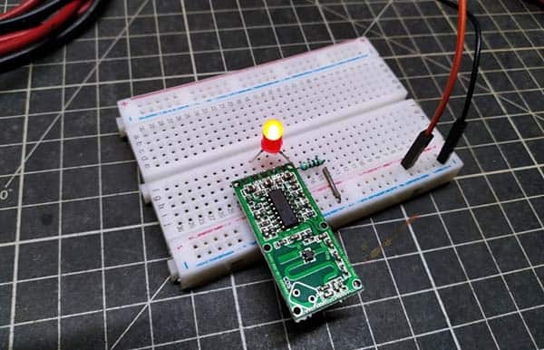
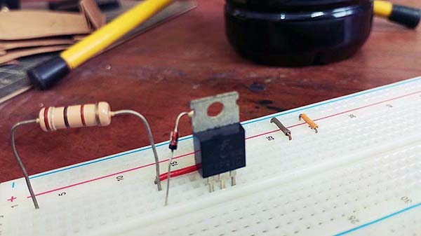
With nothing serious to implement, I set up a crude model of the transistor shunt regulator on a breadboard to start my tests. Needless to say, the components were chosen without much thought – I just picked some parts lying around my messy workbench and that is it.
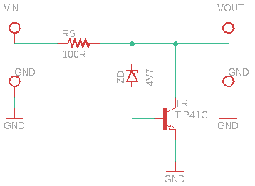
Its circuit diagram is shown below.
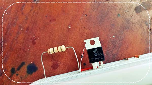
Its components are listed below.
- TIP41C Power Transistor
- 1N5230 4.7V/0.5W Zener Diode
- 100Ω/1W Resistor
Now onto some shunt regulator basics…
A basic shunt regulator, consists of a series resistor and a Zener diode, is simple and cheap but it is usually suitable only for relatively small currents and fairly low voltages.
The current that can be handled by the simple shunt regulator is limited by the maximum current rating of the Zener diode. But there are clever ways of increasing the maximum current capability of a shunt regulator, and one typical method is the utilization of a power transistor which is ready to handle a current much larger than the Zener diode, as depicted in my schematic above.
Time to stick with the textbook math…
- VL: Load Voltage = VZ + VBE = 4.7V + 0.7V = 5.4V
- IL: Load Current (@150Ω Load, for example) = 5.4V / 150Ω = 36mA
- IRS: Current via series resistor RS (VIN@12V, for example) = 12V – 5.4V / 100Ω = 66mA
- IC: Collector Current = 66mA – 36mA = 30mA
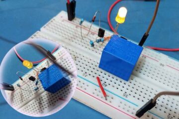
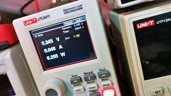
I tested a breadboard mock up in different ways to evaluate its performance. Most tests were performed using a programmable lab power supply and a digital electronic load (see below). There were some minor drifts in the outcomes due to the component tolerances (and my frail breadboard wiring), but that does not mean the breadboard setup is bad, it did its job fairly well.
Finally, you may find it interesting to get some random pointers about this large current transistor shunt regulator…
- The voltage drop across the series resistor primarily depends upon the load current
- The output voltage (load voltage) appears will be the difference between the applied voltage and the series resistor voltage drop
- If the input voltage increases, the output voltage also increases for a while. But the increased current flow through the series resistor introduces a higher voltage drop across it, and this maintains a stable output voltage responsively
- If the load current increases, base current (and collector current) of the transistor decreases. As a result, less current is shunted, the load current becomes larger, thereby maintaining the voltage across the load reasonably stable. The reverse happens if the load current decreases
- The BJT can be any jellybean NPN power transistor, just make sure it can happily handle the requisite shunt current
- Remember to choose a Zener diode 0.7V lower than the load voltage you want due to the 0.7V VBE of the transistor
- To find a Zener diode’s maximum current, simply divide its power rating by its voltage. Note, it would be better to trial the Zener diode between 10-50% of its maximum power rating