Today we are going to inspect the CD4541B CMOS programmable timer IC. The CD4541B programmable timer chip has a 16-stage binary counter, an integrated oscillator for use with an external capacitor and two resistors, output control logic, and a special power-on reset circuit. It is much the same vintage as the 555 timer chip but the fact that it is still commercially available addresses to its application and flexibility. Also, in my view, this seems to be the most underrated feature-rich timer chip. So, let me share a few key points to help you choose it for your next electronic timer projects.
This 14-Pin IC is designed to operate from 3VDC to 18VDC supply. See its pin assignments below.
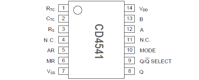
The CD4541 chip includes an internal programmable RC oscillator with a frequency range of DC to 100kHz. By simply connecting a resistor (RTC) to Pin 1 and a capacitor (CTC) to Pin 2, you can setup the internal RC oscillator.
Note that if you are going to use the internal RC oscillator for your timer, you must link the RC network to Pin 3 through a resistor (Rs) that has approximately twice the value of the first resistor (RTC). The formula for the resultant oscillator frequency is f =1/(2.3xRTCxCTC).
An interesting thing here is that this chip contains a timer that can count to one of four values: 2^8,2^10, 2^13, and 2^16 (256, 1024, 8192 and 65536). With external jumpers wired to A (Pin 12) and B (Pin 13) of the chip, you can define which value to count to. The following “division ratio table” copied from the datasheet provides enough details.
| A | B | Number of Counter Stages n | Count 2n |
| 0 | 0 | 13 | 8192 |
| 0 | 1 | 10 | 1024 |
| 1 | 0 | 8 | 256 |
| 1 | 1 | 16 | 65536 |
Here is the CD4541 truth table:
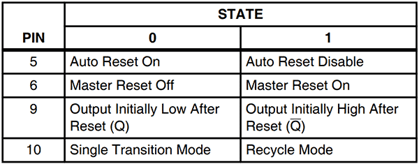
Note at this point that AR (Pin 5) of the chip is responsible for the automatic start of the timer after power is applied. If AR is linked to 0V/GND, the timer will start after power is applied, but if it is linked to VDD, the timer will need to be initiated through a master reset button wired to MR (Pin 6).
Voltage at the output terminal Q (Pin 8) will change according to the timer function. But the initial state of Q can be set by the SELECT (Pin 9). If Pin 9 is connected to 0V/GND, the output will be Low after the start of the countdown and High after the countdown is completed. Likewise, the MODE terminal (Pin 10) sets the single-shot (0)/cyclic (1) timer mode.
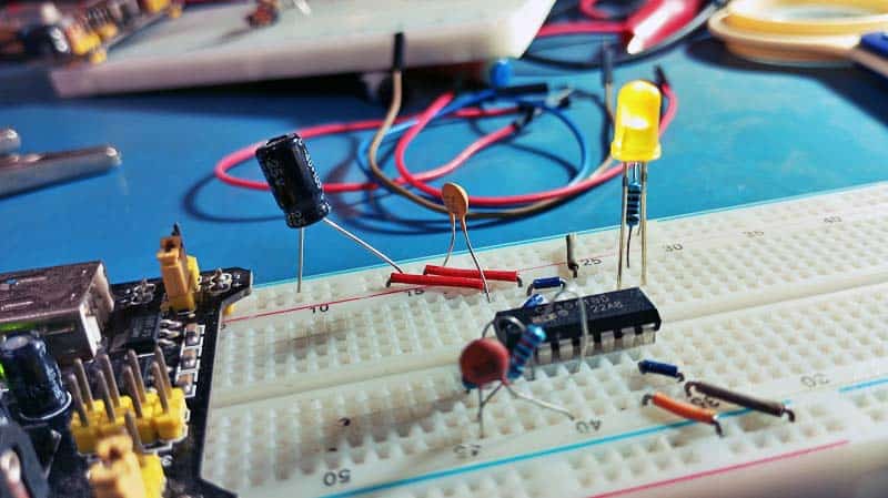
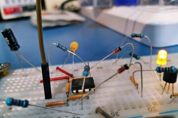
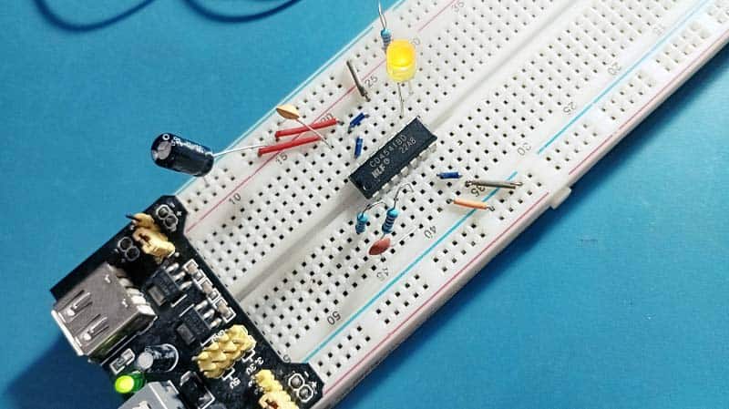
Now see the schematic of a practical CD4541 cyclic timer below (and have a go)…
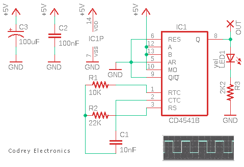
This 5V cyclic timer sample application has RTC as 10KΩ, CTC as 10nF, and Rs as 22KΩ, and the IC is configured for 216 counts.
So, the frequency is f = 1/(2.3 x 10000 x 1×10-8) = 4347.826 Hz
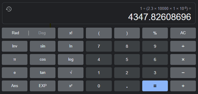
Dividing this into the count value less one power gives 215/4347.826 = 7.536
So, the timing duration is about 7.5 seconds. Once the power has been turned on, the counter starts automatically, and once finished the LED is lit for a finite period, and this process iterates infinitely. Note that a trim pot in lieu of the 10KΩ fixed resistor R1 lets you change the frequency as desired.
For my tests, I used a standard 5VDC breadboard power supply. Just a note here, the output of the IC (Pin 8) can sink or source current to drive little loads like LEDs. Check the datasheet for more specific parameters as the output current depends on the actual VDD that is selected.
Obviously, if you want to drive a relay instead of just using an LED you should add a BJT/MOSFET based driver circuit here. I have not tested it in practice yet, so will not give any related circuit ideas at this time.
That is all for now. As always, thank you for reading and I look forward to your comments and suggestions. Well, now you have something new to make. Enjoy!