Many of the newer robotic toys for kids now use 1.5V AA or AAA batteries as the power source. And it is a common practice to wire them in series to get a healthy 6VDC output. Often, this method is far better than using a weak 6F22 9V battery (at least in my opinion). However, like most other power sources, the first thing this setup demands is a low-battery disconnect circuit. So, in this post we will see how to set up a primitive 6V battery guard relay module.
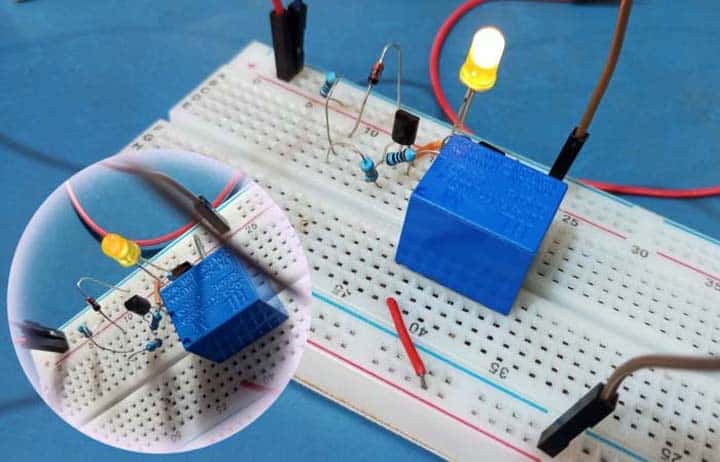
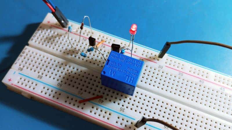
Let us start with a bit funny experimental circuit. As you can see below the idea is centered around a couple of familiar transistors and a few other lame components.
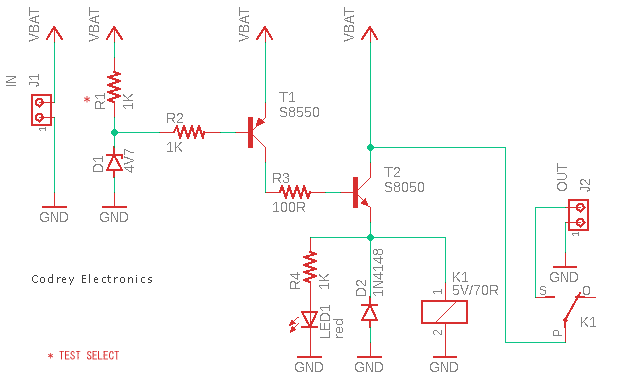
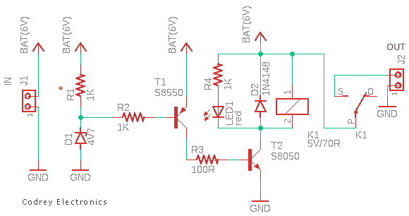
When the input voltage from the battery (VBAT/J1) falls below a certain level, the relay (K1) in this undervoltage (low battery) detector circuit turns off, thus disconnecting the positive battery rail from the output load (OUT/J2). Note that the relay is normally in the energized state, thus delivering power to the load. The relay-on indicator (LED1) is optional and can be omitted.
As you might have guessed, the 4.7V zener diode (D1) in this circuit is the most responsible component in deciding the relay drive thresholds (on and off). Since zener diodes have some drifts though not readily apparent, you may need to modify this basic circuit configuration slightly to get reliable performance as anticipated. Note that the zener voltage drifts slightly with temperature and zener current (Zener diodes around 5V have the best stability). Most zener diode datasheets are usually a bit murky on this one, but here is a zener diode datasheet just for your quick reference.
Now to some common zener diode terms:
- Zener Effect: The reverse breakdown effect in diodes in which breakdown occurs at reverse voltages below 5V
- Zener Breakdown Voltage: The reverse bias voltage at which the breakdown occurs
- Zener Knee Voltage: The voltage in reverse bias condition while reverse breakdown occurs
- Zener Knee Current: The reverse current that flows through the zener diode while at the breakdown voltage
- Zener Impedance: The impedance of a zener diode while at the breakdown voltage
To learn more about Zener diodes: Zener Theory and Design Considerations
Admittedly, there is not much to say about the transistor configuration in this design. However, it might be worth Googling the following terms thoroughly to get a better understanding of the quite common dual-transistor configurations.
- Darlington Pair
- Compound/Complementary Pair
- Sziklai Pair
Actually this post is primarily meant for beginners and self-learners. So, do your own homework and experiments to figure out the pros and cons of the design idea shown above. I am going to wrap up this post after showing a variant of the same concept. Any missteps?
I hope this short post helps you one way or the other. You have the opportunity to learn from everything around you, even from the mistakes of others (and your own). Give your opinion about what you just read, and leave your comments for me in the box below!